
Method and apparatus for deriving at least one audio signal from two or more input audio signals

a technology of audio signal and input audio, applied in the field of audio signal processing, can solve the problems of greater undesirable crosstalk between the output signals of the additional decoder, the 3 db separation between the signals associated with adjacent directions, and the disadvantage of crosstalk among the decoded audio signals

Inactive Publication Date: 2005-11-29
DOLBY LAB LICENSING CORP
View PDF11 Cites 22 Cited by
  • Summary
  • Abstract
  • Description
  • Claims
  • Application Information

AI Technical Summary

Benefits of technology

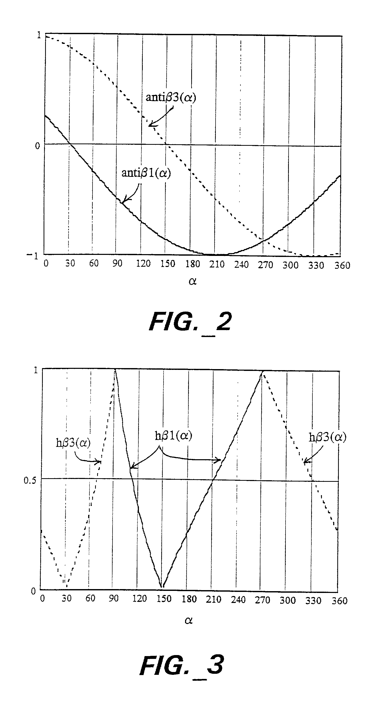
[0038]For an N-output decoder, there are N triplets of β1, β2 and β3, and hence the process and arrangement just described is carried out N times to yield N outputs substantially without unwanted crosstalk between them.

Problems solved by technology

The decoded signals are approximations because matrix decoders suffer the well-known disadvantage of crosstalk among the decoded audio signals.
However, the inherent crosstalk in matrix decoders typically results in only 3 dB separation between signals associated with adjacent directions.
However, such additional decoder output signals suffer from greater undesirable crosstalk than the basic four outputs of the decoders in said Fosgate applications.

Method used


Image

  • Method and apparatus for deriving at least one audio signal from two or more input audio signals
  • Method and apparatus for deriving at least one audio signal from two or more input audio signals
  • Method and apparatus for deriving at least one audio signal from two or more input audio signals

Examples


Embodiment Construction

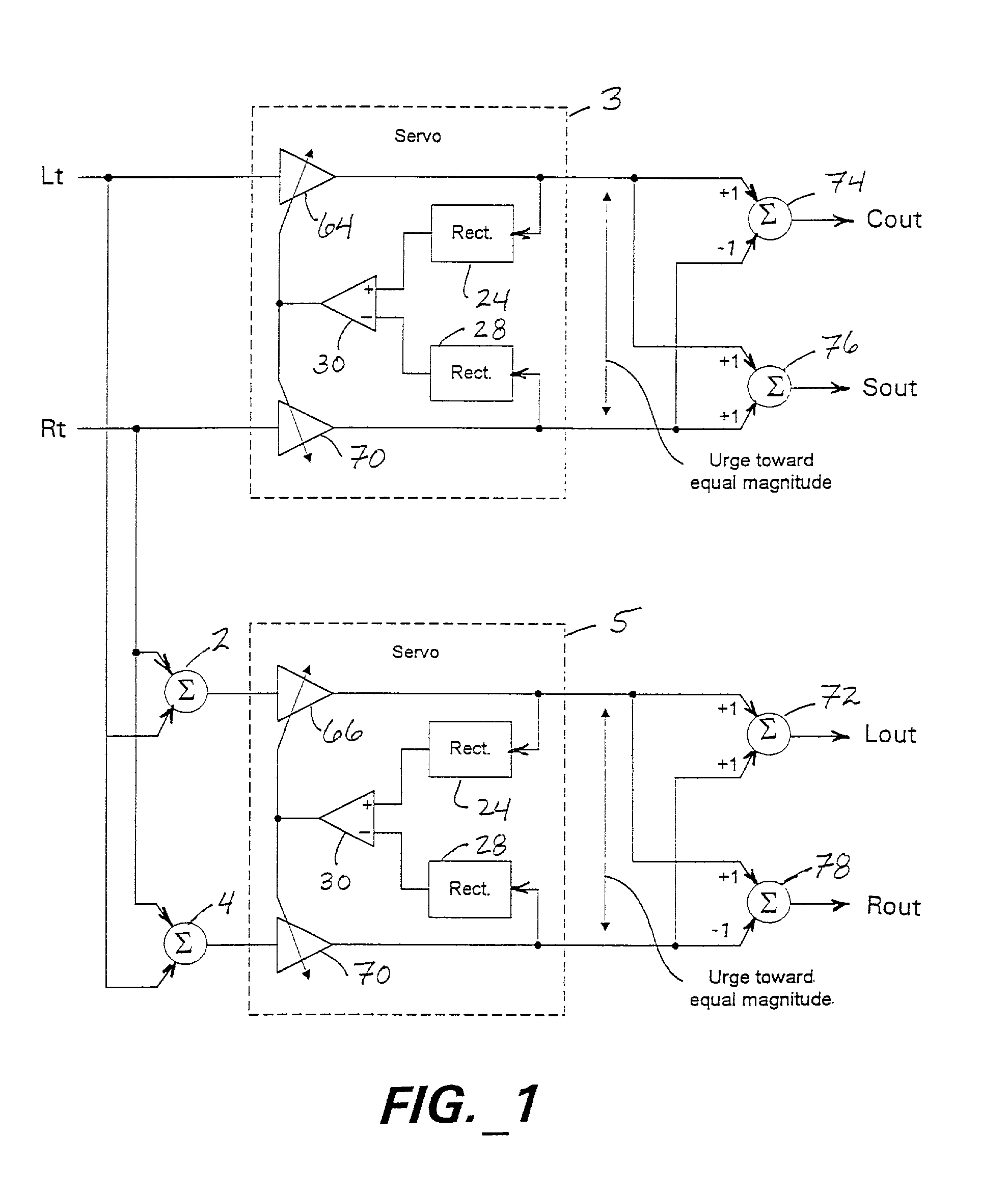
[0105]FIGS. 13 through 18 and their related descriptions are based on FIGS. 1 through 6 and their related descriptions in said Fosgate patent applications. The following descriptions of FIGS. 13 through 18 provide further details of the four-output, two-input decoder described in said Fosgate applications. Certain aspects of those decoders are relevant to the present invention and form a part of the disclosure of the present invention.

[0106]A passive decoding matrix is shown functionally and schematically in FIG. 13. The following equations relate the outputs to the inputs, Lt and Rt (“left total” and “right total”):

Lout=Lt  (Eqn. 26)

Rout=Rt  (Eqn. 27)

Cout=½·(Lt+Rt)  (Eqn. 28)

Sout=½·(Lt−Rt)  (Eqn. 29)

[0107]The center output is the sum of the inputs, and the surround output is the difference between the inputs. Both have, in addition, a scaling; this scaling is arbitrary, and is chosen to be ½ for the purpose of ease in explanation. Other scaling values are possible. The Cout output ...


PUM


Abstract

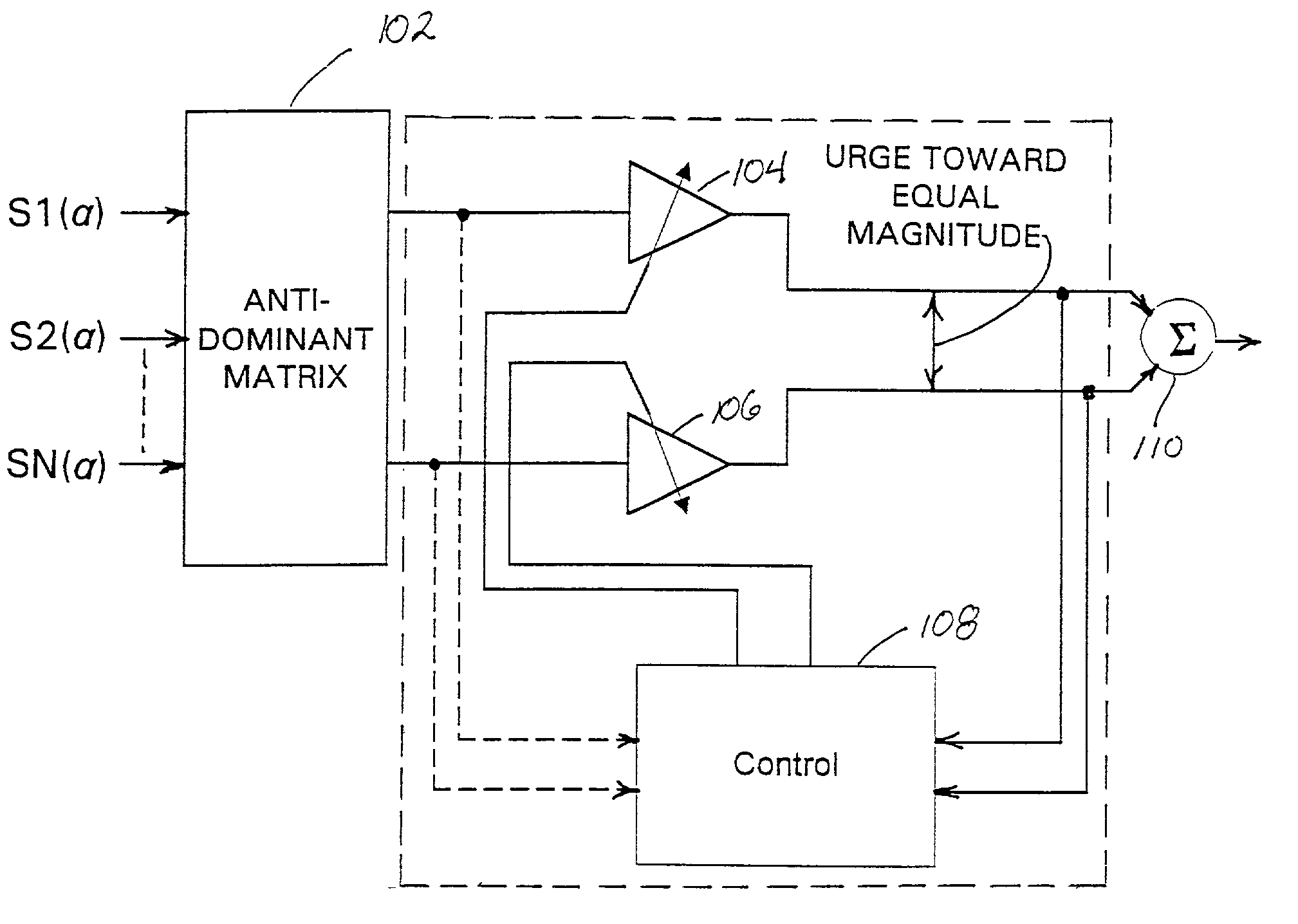
A multidirectional audio decoder using an “adaptive” audio matrix derives at least one of a plurality of output audio signals from two or more directionally-encoded audio input signal streams (S1(α), S2(α), . . . SN(α), wherein α is the encoded angle of a source audio signal. Each output signal is associated with a principal direction β. In order to generate each output signal, a pair of intermediate signals (“antidominant” signals) are generated, constituting the antidominant signal for each of the two adjacent principal output directions of the decoder. The antidominant signal for any arbitrary principal (or “dominant”) direction is the combination of input signals having coefficients such that the combination goes to zero for that dominant direction. Amplitude control is applied to the two antidominant signals to deliver a pair of signals having substantially equal magnitudes that are additively or subtractively combined to provide the output audio signal associated with a principal direction. The pair of signals that are combined include passive matrix components. In an alternative embodiment, passive matrix components for the output signal are derived instead by applying the input audio signals to a passive matrix and by combining the passive matrix components with pairs of amplitude controlled versions of the antidominant signals that do not include passive matrix components. For sources from one direction at a time, there is little or no unwanted crosstalk into outputs that should be silent (ie., there is substantially no signal in outputs other than the two representing directions adjacent to the desired direction, except when the desired direction happens to correspond to that of an output, in which case there is a signal in substantially only that output).

Description

CROSS REFERENCE TO RELATED APPLICATIONS[0001]This application is a continuation-in-part of copending U.S. patent application Ser. No. 09 / 454,810 of James W. Fosgate, filed Dec. 3, 1999 and copending U.S. patent application Ser. No. 09 / 532,711 of James W. Fosgate, filed Mar. 22, 2000.FIELD OF THE INVENTION[0002]The invention relates to audio signal processing. In particular, the invention relates to “multidirectional” (or “multichannel”) audio decoding using an “adaptive” (or “active”) audio matrix that derives at least one audio signal stream (or “signals” or “channels”) from two or more directionally-encoded audio input signal streams (or “signals” or “channels).BACKGROUND OF THE INVENTION[0003]Audio matrix encoding and decoding is well known in the prior art. For example, in so-called “4-2-4” audio matrix encoding and decoding, four source signals, typically associated with the same four cardinal input and output directions (such as, for example, left, center, right and surround o...

Claims


Application Information

Patent Timeline
Patent Type & Authority Patents(United States)
IPC IPC(8): G10L19/008G10L19/02H04S3/02
CPCH04S3/02
Inventor GUNDRY, KENNETH J.FOSGATE, JAMES W.
Owner DOLBY LAB LICENSING CORP
Learn More