
Low profile active shock module prosthesis

a shock module and low-profile technology, applied in the field of low-profile shock module prosthesis, can solve the problems of unrestricted compliance, undesirable, and few, if any, are designed to be compact enough for patients with long residual limbs, so as to reduce the overall height of the shock module and improve the fit. , the effect of low profil

Inactive Publication Date: 2005-11-29
OSSUR HF
View PDF83 Cites 143 Cited by
  • Summary
  • Abstract
  • Description
  • Claims
  • Application Information

AI Technical Summary

Benefits of technology

The present invention provides an impact and torque absorbing prosthetic shock module for a low profile prosthesis to accommodate amputees with long residual limbs. The shock module comprises inner and outer support members that are coaxially supported relative to one another and capable of relative rotation and axial translation. The shock module also comprises a resilient element that resists axial displacement of the support members, and a torque-resisting cuff that provides torsional resistance to relative rotational motion between the support members. The shock module can be precompressed to reduce its overall height, and the lower support member can extend into the space surrounded by the torque-resisting cuff. The invention also provides an adapter for attaching the shock module to a stump-supporting socket or intermediate device, and a prosthetic foot member that has a ground contacting portion adapted to contact a ground surface. The shock module can be used in a lower limb prosthesis that is designed to have a low profile and provide improved shock absorption.

Problems solved by technology

Unrestrained compliance, however, is undesirable, as the foot would be free to twist unnaturally.
Due to the vertical height of some of the pylons, those shock-absorbing prostheses cannot accommodate the shin and calf of an amputee with a long residual limb.
Thus, although the prior art illustrates many impact absorbing prostheses, few, if any, are designed to be compact enough for use by patients with long residual limbs.
Furthermore, none of the prior art sets forth a lower limb prosthesis for amputees with long residual limbs that can provide both impact absorption and rotational compliance with torsion-resistance.

Method used


Image

  • Low profile active shock module prosthesis
  • Low profile active shock module prosthesis
  • Low profile active shock module prosthesis

Examples


Embodiment Construction

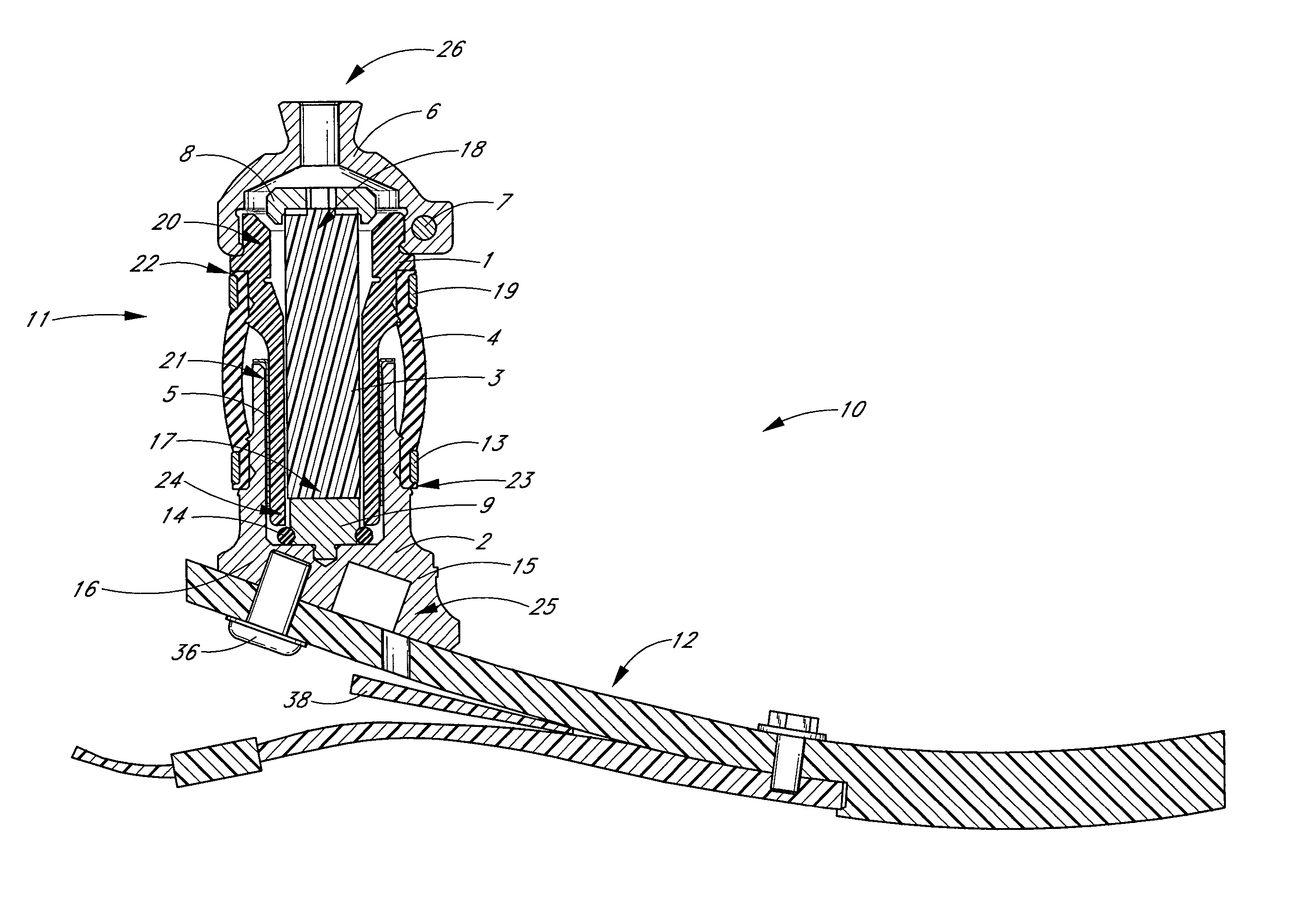
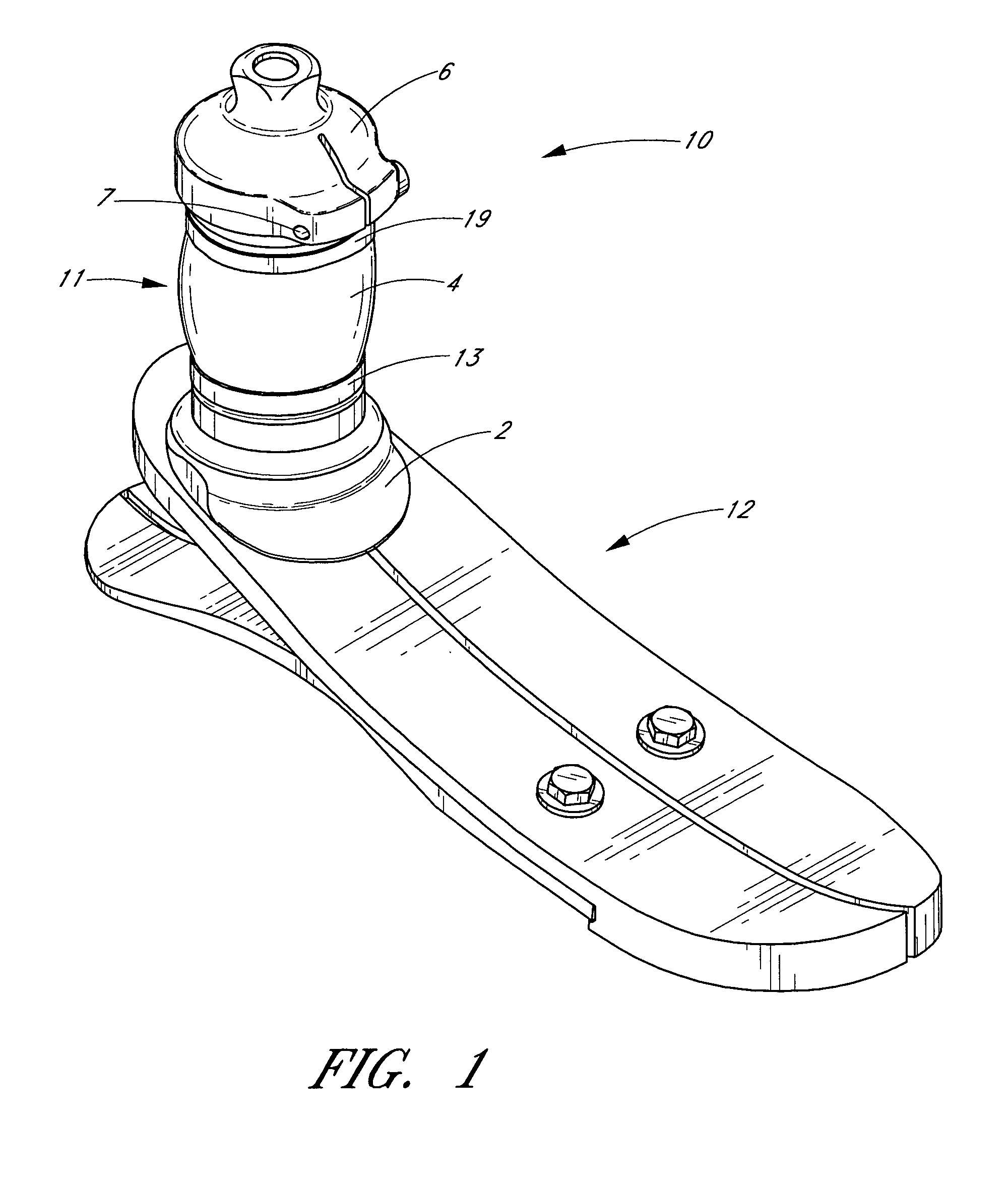
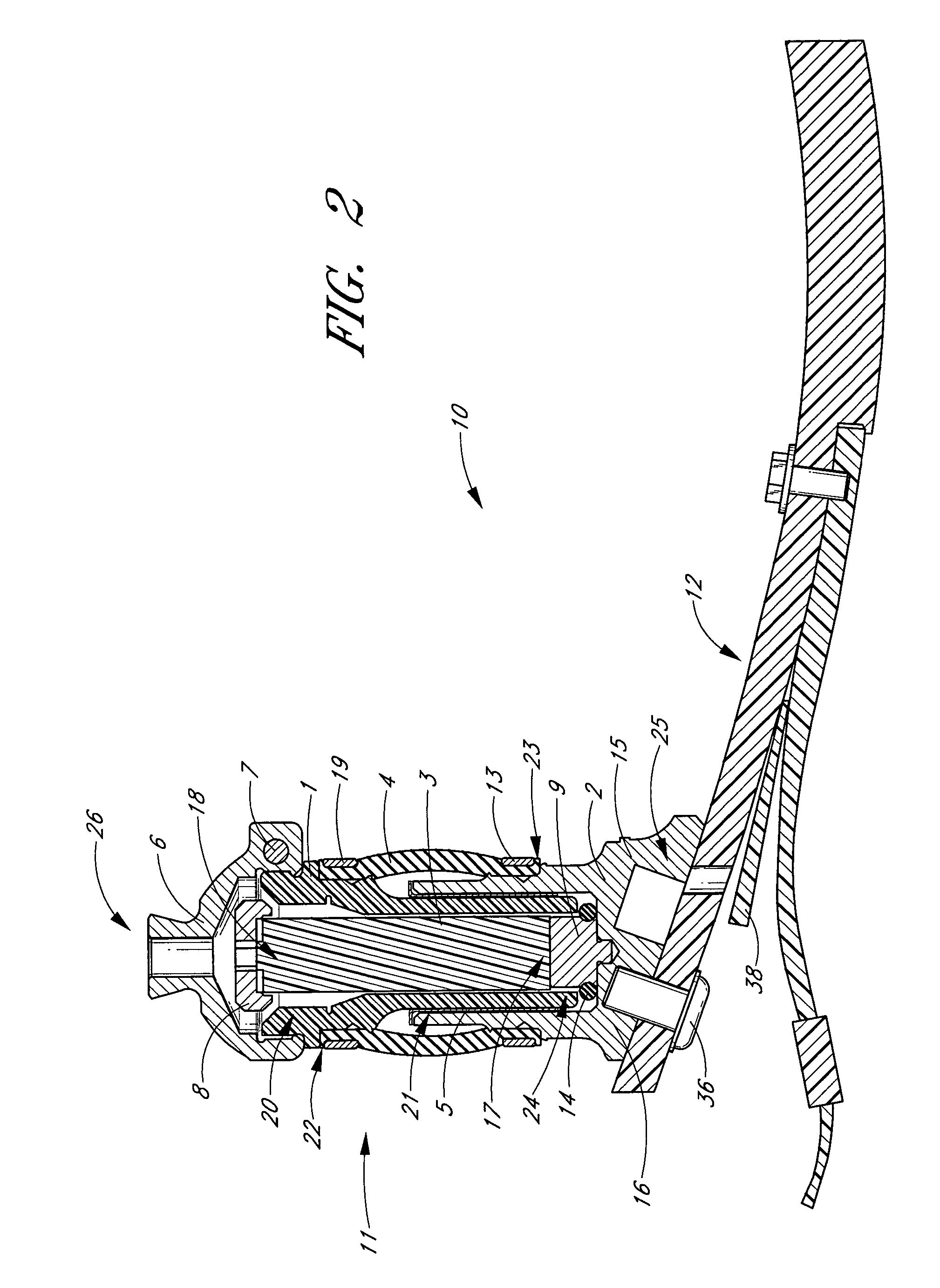
[0025]FIGS. 1–4 show one embodiment of a lower limb prosthesis 10 comprising a shock module 11. For purposes of illustration the prosthesis 10 is shown as also comprising a prosthetic foot 12 with a wedge piece 38, in this case an LP VariFlex® foot available from Össur North America, Inc. of Aliso Viejo, Calif. It will be appreciated that the cross-section of the foot shown in FIGS. 2, 4, and 5 is purely illustrative, and does not include the slot which may bifurcate the foot in certain embodiments. The LP VariFlex® foot is described in further detail in Applicant's application entitled “Low Profile Prosthetic Foot,” Ser. No. 10 / 642,125, filed on Aug. 15, 2003, the entirety of which is hereby incorporated by reference. It will of course be appreciated that shock module 11 can be used with any desired prosthetic foot. In certain preferred embodiments, the prosthetic foot 12 is low profile, and in one embodiment has a height h1, shown in FIG. 4, not greater than about 50 mm.

[0026]As s...


PUM


Abstract

In one embodiment, an impact and torque-absorbing module for a low profile lower limb prosthesis comprises two support members telescopingly engaged to permit axial and rotational motion therebetween. A resilient element resists axial displacement of the two support members, and a torque resisting cuff resists rotational displacement of the two support members. Precompression of the resilient element can reduce the size of the shock module making it more compact. The resilient element can also be replaced allowing adjustment of the shock absorption.

Description

BACKGROUND OF THE INVENTION[0001]1. Field of the Invention[0002]Embodiments of the present invention relate to lower limb prostheses in general, and, in certain embodiments, to a low profile shock module prosthesis having a resilient element and a torque-resisting cuff permitting rotational compliance between the lower leg and foot.[0003]2. Description of the Related Art[0004]Various types of lower limb prostheses are known in the prior art. Such devices generally include some form of attachment for coupling the device to the dorsal end of the limb and for extending to the ground to provide body support. Moreover, these devices generally constitute attempts to simulate the structure and / or the performance of the human leg and foot.[0005]The various prostheses known in the prior art include some prostheses designed for people who have long residual limbs. For these patients, the calf and shin functions as the stump for prosthetic purposes. Thus, any prosthetic device utilized by the ...

Claims


Application Information

Patent Timeline
Patent Type & Authority Patents(United States)
IPC IPC(8): A61F2/00A61F2/50A61F2/66
CPCA61F2/66A61F2002/30365A61F2002/30372A61F2002/5003A61F2002/5007A61F2002/5055A61F2002/6621A61F2002/6642A61F2002/6664A61F2002/6685A61F2220/0033
Inventor LECOMTE, CHRISTOPHE GUYRAGNARSDOTTIR, HEIDRUN GIGJA
Owner OSSUR HF
Learn More