
Method and apparatus for refinably accurate localization of devices and instruments in scattering environments

a scattering environment and localization technology, applied in the field of refinably accurate localization of devices and instruments in scattering environments, can solve the problems of significant loss of accuracy in position and/or orientation determination, standard imaging methods such as x-ray, ct, or mri may not provide adequate information for navigation, and may not provide sufficient accuracy. the effect of accurate approximation and refinemen

Inactive Publication Date: 2005-11-29
STEREOTAXIS
View PDF11 Cites 166 Cited by
  • Summary
  • Abstract
  • Description
  • Claims
  • Application Information

AI Technical Summary

Benefits of technology

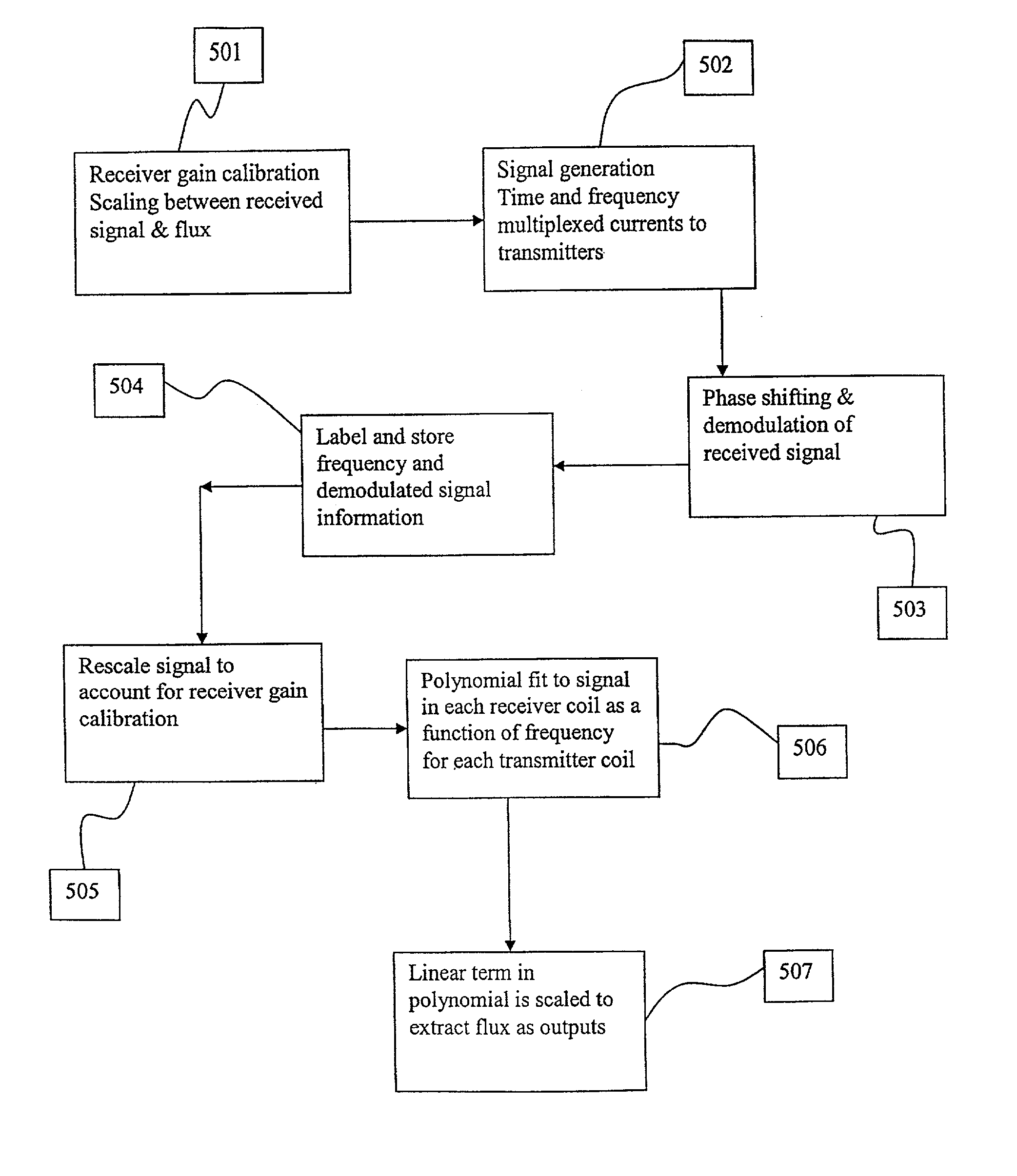
[0006]Furthermore, it is necessary that each transmit coil be able to transmit at at least three distinct frequencies. By having each coil transmit at a larger number of distinct frequencies, the accuracy of the localization can be refined successively to the extent desired by suitable processing. The sensors may be any magnetic field sensors such as coils, Hall probes and other devices known to those skilled in the art. The signal processing discards pieces of the signal that arise from external scattering, leaving behind a “true” or desired signal that is, by the use of an increasing number of transmit frequencies, an increasingly accurate approximation to the signal that would be received in a scatter-free environment. This process is convergent and fast, even in a “worst case” situation where the receiver coil and the scatterer are geometrically maximally coupled. Furthermore, the entire process can be carried out in real time, meaning that as long as angular velocities associated with movements of conductors in the environment are significantly smaller than the circular frequencies of the electromagnetic radiation used, changes in environment such as moving metallic equipment are always automatically accounted for. The analysis also provides design methods whereby the accuracy can be further improved.
[0007]Thus, the method of this invention provides for accurate and fast localization by electromagnetic means of devices, including but not limited to medical devices, within a three dimensional region such as within a patient's body, which is not significantly affected by the presence of metal near the region of interest.

Problems solved by technology

Standard imaging methods such as x-ray, CT, or MRI may not provide adequate information for use in navigation.
They typically suffer from a lack of sufficient accuracy due to inherent methodological problems, inhomogeneities in the environment, or interference from the environment.
The use of time-dependent electromagnetic fields for localization purposes suffers from a significant drawback—in the presence of external electromagnetic scatterers, such as metals, in the environment that can support induced currents, backscatter from these metals can alter the signals received by the receiver coils and lead to significant loss of accuracy in determination of the position and / or orientation.
In cases where the external environment is changing, such as moving metals, these changes in signal are not predictable in advance.

Method used


Image

  • Method and apparatus for refinably accurate localization of devices and instruments in scattering environments
  • Method and apparatus for refinably accurate localization of devices and instruments in scattering environments
  • Method and apparatus for refinably accurate localization of devices and instruments in scattering environments

Examples


Embodiment Construction

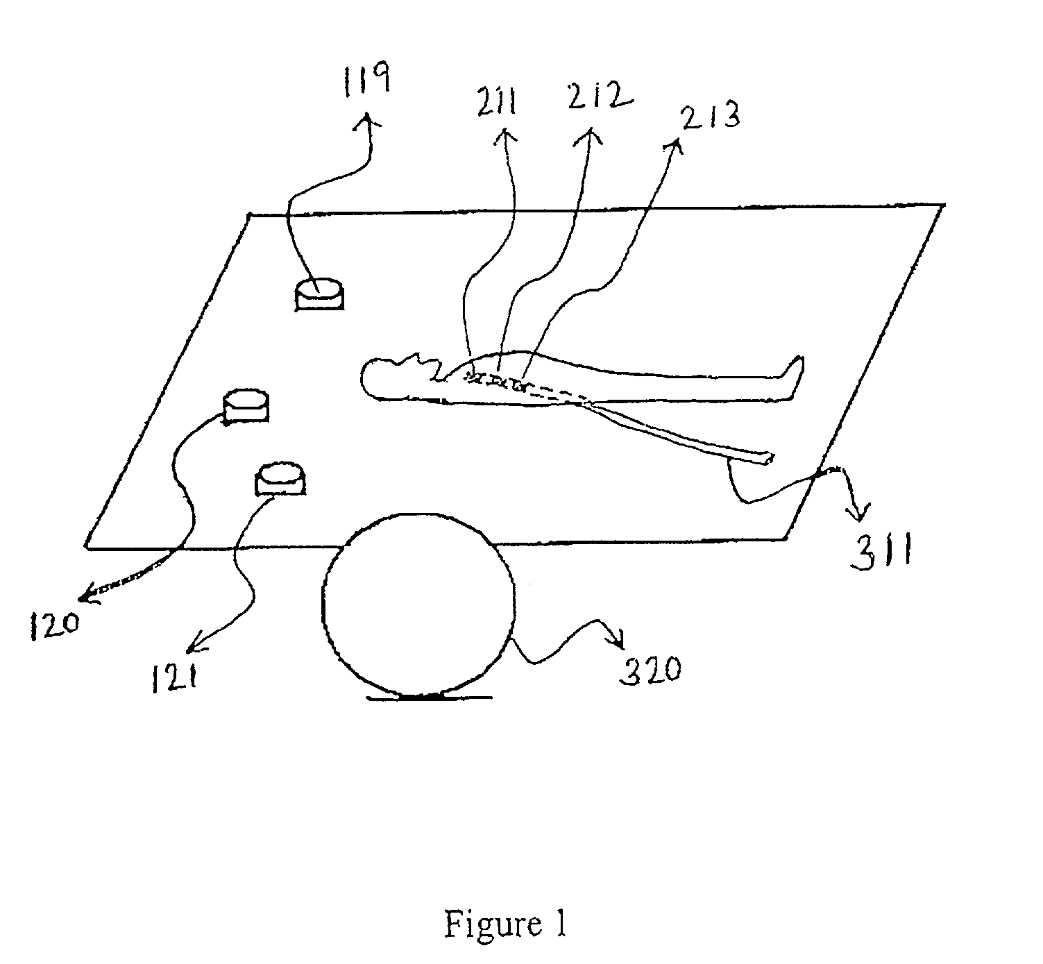
[0013]The localization method described herein is based on the use of multiple transmitters (e.g., coils), at least three in number, each fixed at a known spatial location and capable of transmitting electromagnetic radiation at at least three distinct frequencies. Preferably the transmission method uses driving currents in each coil with the time dependence of the currents being sinusoidal at each of the distinct frequencies.

[0014]One or more receivers (such as coils or other magnetic field sensor such as Hall probes) is located within or on the device whose localization is desired. While receiver coils are described in this preferred embodiment, it should be understood that this invention includes the use of other magnetic field sensors. An example of a medical device where such coils could be used is a catheter with receiving coils mounted at or near the catheter tip. Due to the time dependence of the transmitted magnetic field, the changing magnetic flux in the receiver coils pr...


PUM


Abstract

A method of localizing a device, medical or otherwise, within a three dimensional environment, the method comprising: (a) transmitting time varying magnetic fields from at least three transmitters, (b) receiving the transmitted electromagnetic radiation as induced voltage signals from at least one receiver mounted on or within said device, and (c) a processing scheme for processing said received voltage signals in order to extract position and orientation localization information for said device, said processing scheme including correction for conducting materials in the vicinity by the use of information gathered from at least three distinct transmission frequencies for each of said transmitters.

Description

FIELD OF THE INVENTION[0001]This invention relates to localization, (the determination of position and / or orientation) of an instrument within a three dimensional region in the presence of external scatterers of electromagnetic fields, and in particular to the localization of a medical device in a patient's body.BACKGROUND OF THE INVENTION[0002]In the context of medical procedures, it is often necessary to determine the position and / or orientation of a medical device within a patient's body. For example to safely and accurately navigate the distal tip of a catheter through the body, it is desirable to know the position and orientation of the catheter. Standard imaging methods such as x-ray, CT, or MRI may not provide adequate information for use in navigation. Similarly, methods such as image reconstruction and processing, electrical potential measurements, ultrasound and electromagnetic measurements have been used for this purpose. They typically suffer from a lack of sufficient ac...

Claims


Application Information

Patent Timeline
Patent Type & Authority Patents(United States)
IPC IPC(8): A61BA61B5/05A61B5/06A61B19/00G01D5/20G01V3/10
CPCA61B5/06A61B19/5244G01D5/2086G01V3/104A61B2019/5251A61B34/20A61B2034/2051A61B5/062
Inventor VISWANATHAN, RAJU R.
Owner STEREOTAXIS
Learn More