
Apparatus and methods for forming internally and externally textured tubing

a technology of external and internal surfaces and tubing, which is applied in the direction of metal rolling arrangements, metal-working apparatuses, etc., can solve the problems of increasing the heat transfer rate across the tube, and achieve the effects of reducing the diameter, increasing the surface area, and facilitating the tube attachmen

Inactive Publication Date: 2005-11-29
PACKLESS METAL HOSE
View PDF47 Cites 31 Cited by
  • Summary
  • Abstract
  • Description
  • Claims
  • Application Information

AI Technical Summary

Benefits of technology

[0016]Inner and outer surfaces of a tube may be simultaneously textured with a texturing machine. The texturing machine may include an outer knurling device and an inner knurling device. The knurling devices may be used to form grooves in inner and outer surfaces of a tube. The depth of the grooves may be less than about 35 mils (0.035 inches), and are preferably less than about 25 mils. The depth of the grooves may be greater than about 4 mils. The grooves formed in the outer surface of the tube may have a different depth and a different pattern than the grooves formed in the inner surface of the tube. The grooves formed in the surfaces of the tube may increase the surface area of the tube, promote internal mixing of fluid that flows by or through the tube, and inhibit formation of stagnant areas of fluid adjacent to inner and outer surfaces of the tube. The grooves may be formed in a helical pattern about a longitudinal axis of the tube. The angles of the helical patterns formed in the inner and outer surfaces of the tube may be less than about 45° relative to the longitudinal axis of the tube. Angle patterns that are less than about 45° relative to the longitudinal axis of the tube may allow the tube to be used as a heat exchanger element wherein fluid flows by and through the tube in directions that are substantially coaxial with the longitudinal axis of the tube.

Problems solved by technology

Also, directing fluid flow past and through a tube in desired fluid flow patterns may increase the heat transfer rate across the tube.

Method used


Image

  • Apparatus and methods for forming internally and externally textured tubing
  • Apparatus and methods for forming internally and externally textured tubing
  • Apparatus and methods for forming internally and externally textured tubing

Examples


Embodiment Construction

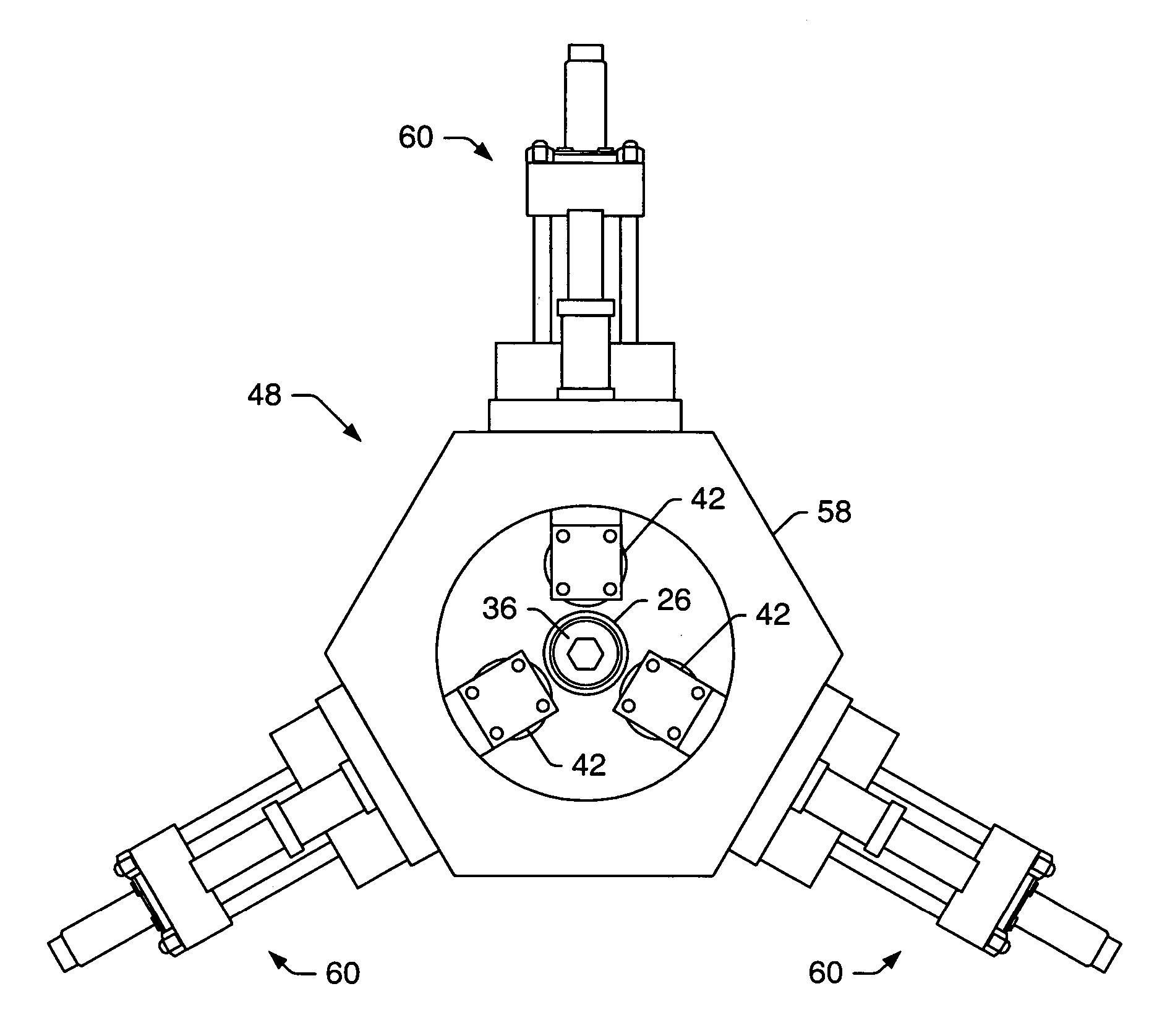
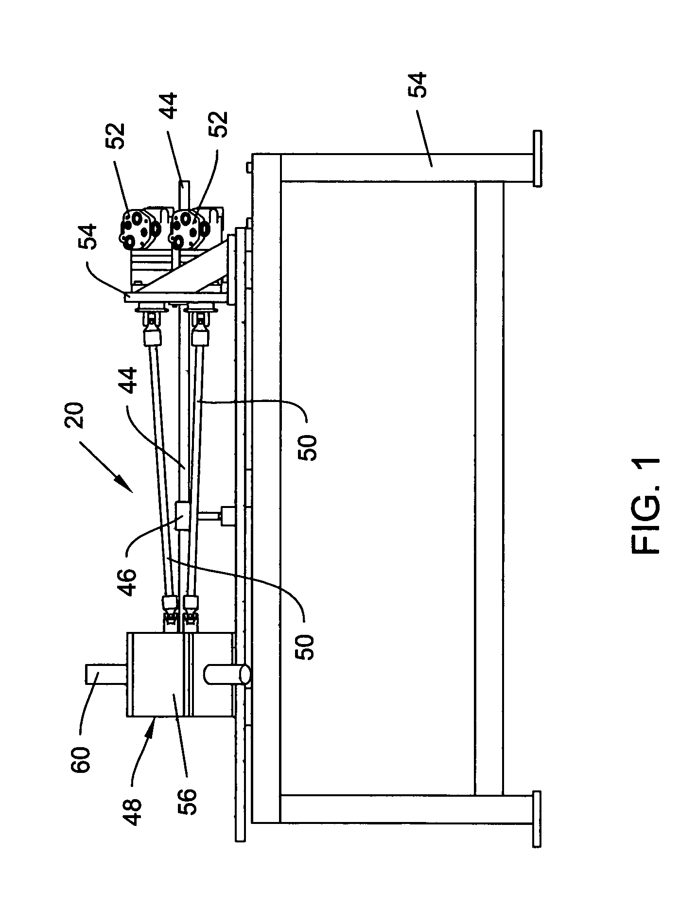
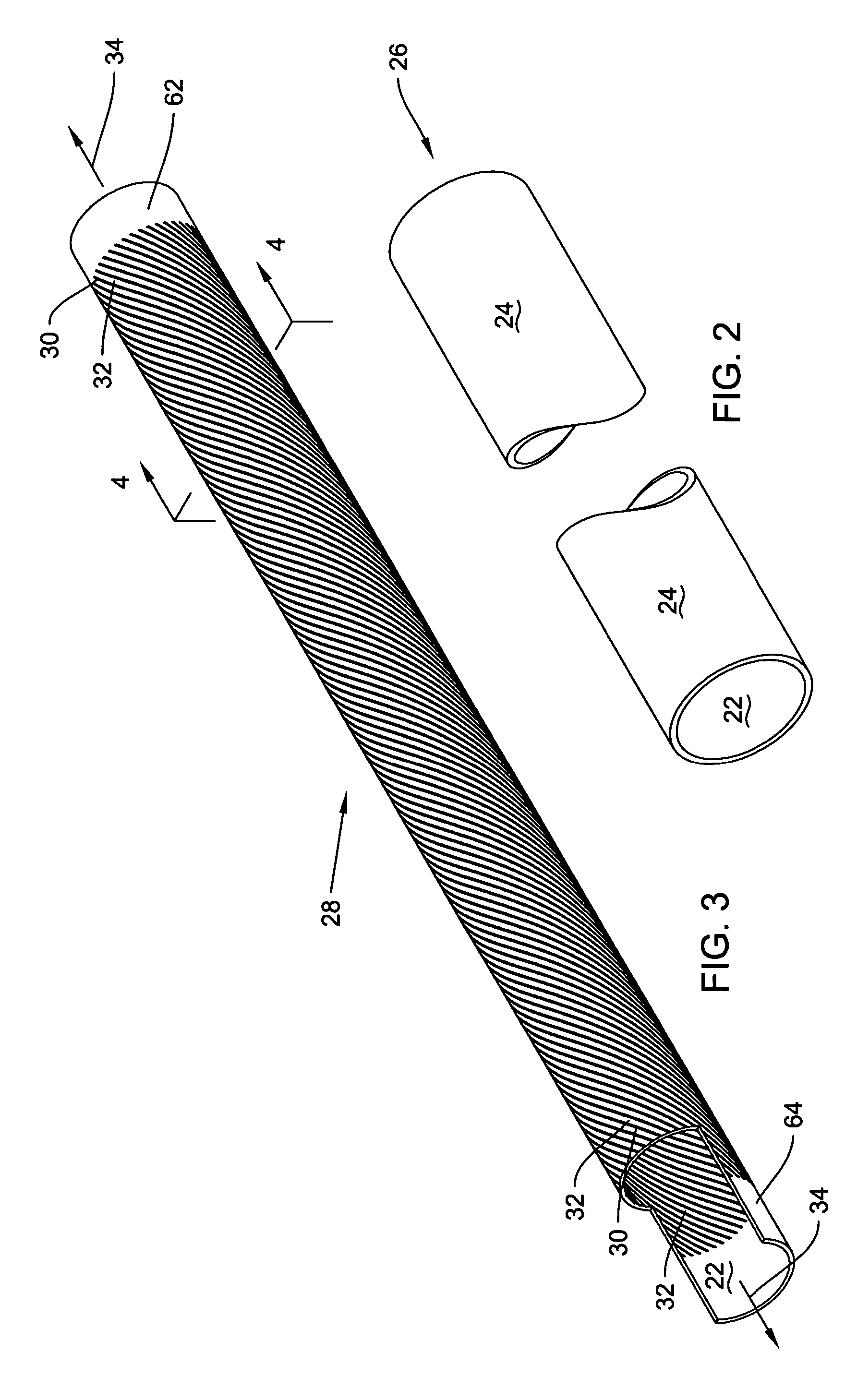
[0047]FIG. 1 shows a top view of texturing machine 20. The texturing machine 20 may be used to texture both inner surface 22 and outer surface 24 of a tube 26. FIG. 2 shows a perspective view of a cylindrical tube 26 that may be used as a starting blank for formation of a textured tube 28. FIG. 3 shows a representation of textured tube 28. A portion of the tube 28 is cutaway to show the texturing of the inner surface 22. FIG. 4 shows a cross sectional view of the tube 28.

[0048]A texturing machine 20 may form a textured tube 28. Cylindrical tube 26 may be used as a starting material to form a textured tube 28. The cylindrical tube 26 may have an outer diameter that is greater than about ¼ of an inch. In an embodiment, the outer tube diameter of the cylindrical tubing stock 26 is about 1½ inches. Preferably, the cylindrical tube 26 is a metallic tube. In certain embodiments, the cylindrical tubing stock 26 may be made of a high thermal conductivity metal; including, but not limited to...


PUM

PropertyMeasurementUnit
Lengthaaaaaaaaaa
Lengthaaaaaaaaaa
Lengthaaaaaaaaaa

Abstract

A machine may produce a tube having textured internal and external surfaces in a single operation. Inner and outer knurling tools may form the textured surfaces. The texturing of the internal and external surfaces may be helical patterns of ribs and grooves. The height of the ribs formed in the internal and external surfaces may be less than about 35 mils. The angles of the patterns relative to a longitudinal axis of the tube may be less than about 45°. The angle of the helical pattern allows textured tubes to be used as heat exchanger elements wherein flow is directed substantially coaxial to the longitudinal axes of the tubes. The helical pattern formed in the external surface may be oriented in a right hand or left hand helical orientation. Similarly, the helical pattern formed in the internal surface may be oriented in a right hand or left hand orientation.

Description

PRIORITY CLAIM[0001]This application is a divisional of Ser. No. 09 / 902,870 U.S. Pat. No. 6,760,972 entitled “Apparatus and Methods For Forming Internally and Externally Textured Tubing” filed on Jul. 10, 2001.[0002]This application claims priority to U.S. Provisional Application No. 60 / 234,458 entitled “Apparatus and Methods For Forming Internally and Externally Textured Tubing,” filed Sep. 21, 2000. The above-referenced provisional application is incorporated by reference as if fully set forth herein.BACKGROUND[0003]1. Field of the Invention[0004]The present invention generally relates to extended surface area tubing. The present invention also generally relates to a machine that produces textured surfaces on both inner and outer surfaces of a tube. The textured surfaces may be patterns of ribs and grooves formed in the inner and outer surfaces of the tube.[0005]2. Description of Related Art[0006]A heat exchanger tube may be used in a process that transfers heat between a first fl...

Claims


Application Information

Patent Timeline
IPC IPC(8): B21C37/20
CPCB21C37/207Y10S72/703Y10T29/49385Y10T29/49384Y10T29/49382Y10T29/49391Y10T29/5166
Inventor ZIFFERER, L. ROBERT
Owner PACKLESS METAL HOSE
Learn More