
Method for controlling process parameters to achieve constant process conditions

a technology of process parameters and process conditions, applied in the direction of adaptive control, process and machine control, instruments, etc., can solve the problem of high level of process knowledge required in order to achieve the effect of constant process conditions

Inactive Publication Date: 2005-11-22
PRIAMUS SYST TECH AG
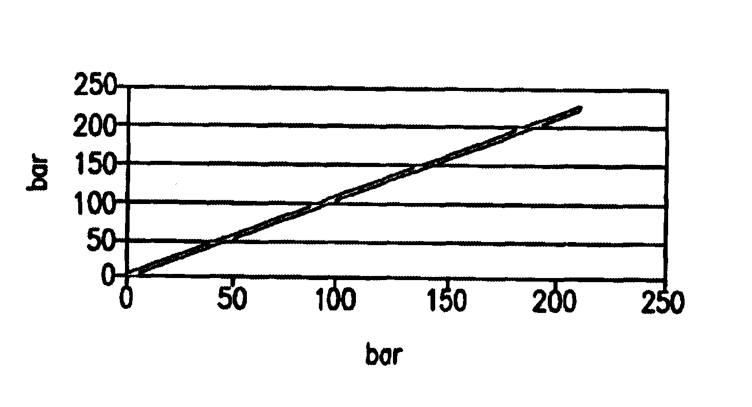
View PDF7 Cites 9 Cited by
  • Summary
  • Abstract
  • Description
  • Claims
  • Application Information

AI Technical Summary

Benefits of technology

[0005]This completely novel and simplifying approach consists primarily in a time-independent consideration of current data and reference data. If the corresponding data of a certain process parameter are plotted against one another and identical spacing is selected for the X axis and the Y axis, the result, in the event of optimum correspondence, is a 45° straight line. If the current profile of the measured data deviates from the reference profile, this can be clearly recognized from this form of presentation and can be eliminated by control measures without the need for further process knowledge.
[0006]In this context, it is irrelevant whether a complete curve or only a partial range is considered. For the user, it is sufficient for this curve profile to be presented, for example, on a display. The user will immediately recognize the deviation and can then initiate a suitable control operation.
[0007]The method according to the

Problems solved by technology

This method has the significant drawback that, even when artificial intelligence is used, a high level of process knowledge is required in order to achieve a reliable solution.

Method used


Image

  • Method for controlling process parameters to achieve constant process conditions
  • Method for controlling process parameters to achieve constant process conditions
  • Method for controlling process parameters to achieve constant process conditions

Examples


Embodiment Construction

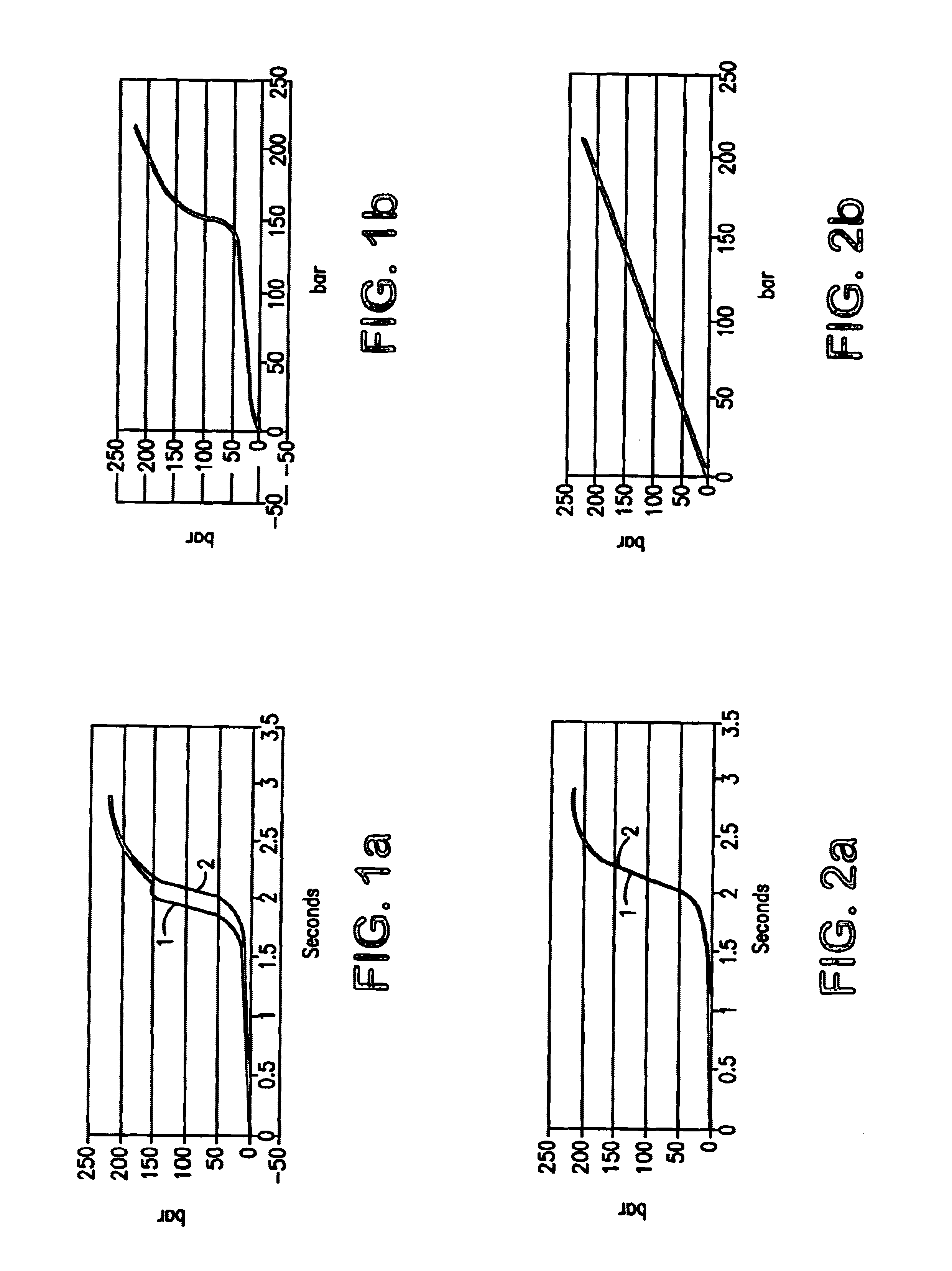
[0013]FIG. 1a illustrates the pressure rise during the filling of two cavities in their runner 1 or runner 2. The illustration takes the form of pressure (bar) against time (seconds). It can be seen that the pressure begins after about 1 second and rises considerably after about 2 seconds in the case of runner 2, with the maximum being reached after about 3 seconds. The profile of the pressure rise in runner 2 is taken as the reference pressure curve. Of course, it would also be possible for the profile of the pressure rise in runner 1 to be taken as the reference curve.

[0014]The pressure profile in runner 1 deviates from the pressure profile in runner 2 in the range between 1.8 seconds and 2.4 seconds. If the pressure profile in runner 1 is now plotted against the pressure profile in runner 2, as shown in FIG. 1b, the result is a fluctuating curve which deviates from a desired straight line.

[0015]A balanced pressure profile in runners 1 and 2 is desired, as illustrated in FIG. 2a. ...


PUM


Abstract

A method for controlling process parameters to achieve constant process conditions, including studying the actual data and reference data independent of time and applying them one on top of the other so that, in the case of optimum match, a 45° straight line is achieved or, in the case of non-match, one tries to achieve a 45° straight line by modifying the process parameters.

Description

BACKGROUND OF THE INVENTION[0001]The invention relates to a method for controlling process parameters in order to obtain constant process conditions.[0002]In conventional control methods aimed at achieving constant process conditions, it is customary for current measurement data to be compared with reference data as a function of time. As the next method step, it is attempted to make the current measurement data correspond to the reference data by controlling the process parameters. This method has the significant drawback that, even when artificial intelligence is used, a high level of process knowledge is required in order to achieve a reliable solution.[0003]It is the object of the present invention to significantly simplify the above method and make it easier for the user to operate the process, so that the method can be carried out even by less well-trained staff.SUMMARY OF THE INVENTION[0004]The foregoing object is achieved by the fact that the current data and reference data ...

Claims


Application Information

Patent Timeline
IPC IPC(8): G05B23/02B28B1/24B22D17/32B29C45/26B29C45/76B29C45/77
CPCG05B13/0285B29C45/77
Inventor FREY, JURGEN
Owner PRIAMUS SYST TECH AG
Learn More