
Color reproducing device

a color reproduction and color technology, applied in the direction of digital output to print units, instruments, digital computer details, etc., can solve the problems of color mismatching, difficult to shoot a subject in one shot, and inability to make data conversion to suit the lighting conditions, etc., to achieve accurate color reproduction

Inactive Publication Date: 2005-11-01
OLYMPUS CORP
View PDF18 Cites 9 Cited by
  • Summary
  • Abstract
  • Description
  • Claims
  • Application Information

AI Technical Summary

Benefits of technology

[0031]It is an object of the present invention to provide a color reproduction device which makes image conversion while referencing image input device information, and color reproduction environment information containing shooting- and observation-time lighting spectral information and information concerning the statistical nature of the spectrum of a subject, allows the image shooting and reproducing sites to be remote from each other, and allows accurate color reproduction even when offset light and environment light vary.

Problems solved by technology

Therefore, a color mismatching problem will arise when an image is shot under a light source different from D50 or when an output image is observed under a light source different from D50.
Thus, on the observer side, no data conversion can be made to suit the lighting.
For this reason, the image input device must be a multi-spectral camera capable of capturing spectral images in many bands, which makes it difficult to shoot a subject in one shot.
In addition, a captured image will involve a large amount of data.
Thus, satisfactory color reproduction is not necessarily achieved even if an output profile is created for the monitor by the conventional technique.
The recreation of the output profile with each variation of the offset light or environment light requires not only expert knowledge but also a large amount of time.

Method used


Image

  • Color reproducing device
  • Color reproducing device
  • Color reproducing device

Examples


first embodiment

[0072]Reference will be made to FIGS. 1 through 7 to describe a color reproduction device of the present invention.

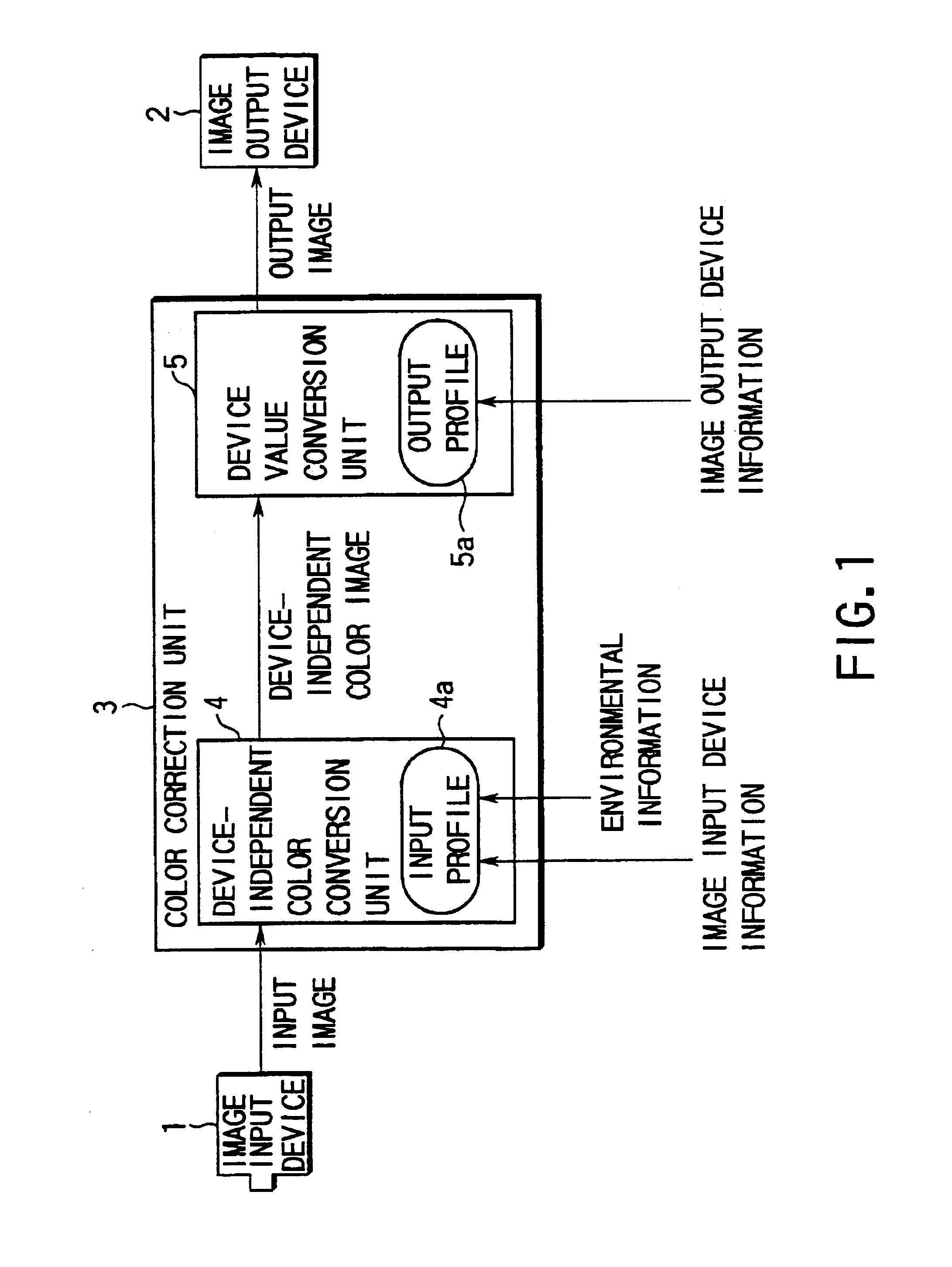
[0073]As shown in FIG. 1, the color reproduction device is composed roughly of an image input device 1 for capturing an image of a subject, a color correction unit 3 for correcting the colors of the image, and an image output device 2 for outputting (displaying or printing) an output image.

[0074]The color correction unit 3 is composed of a device independent color conversion unit 4 and a device value conversion unit 5.

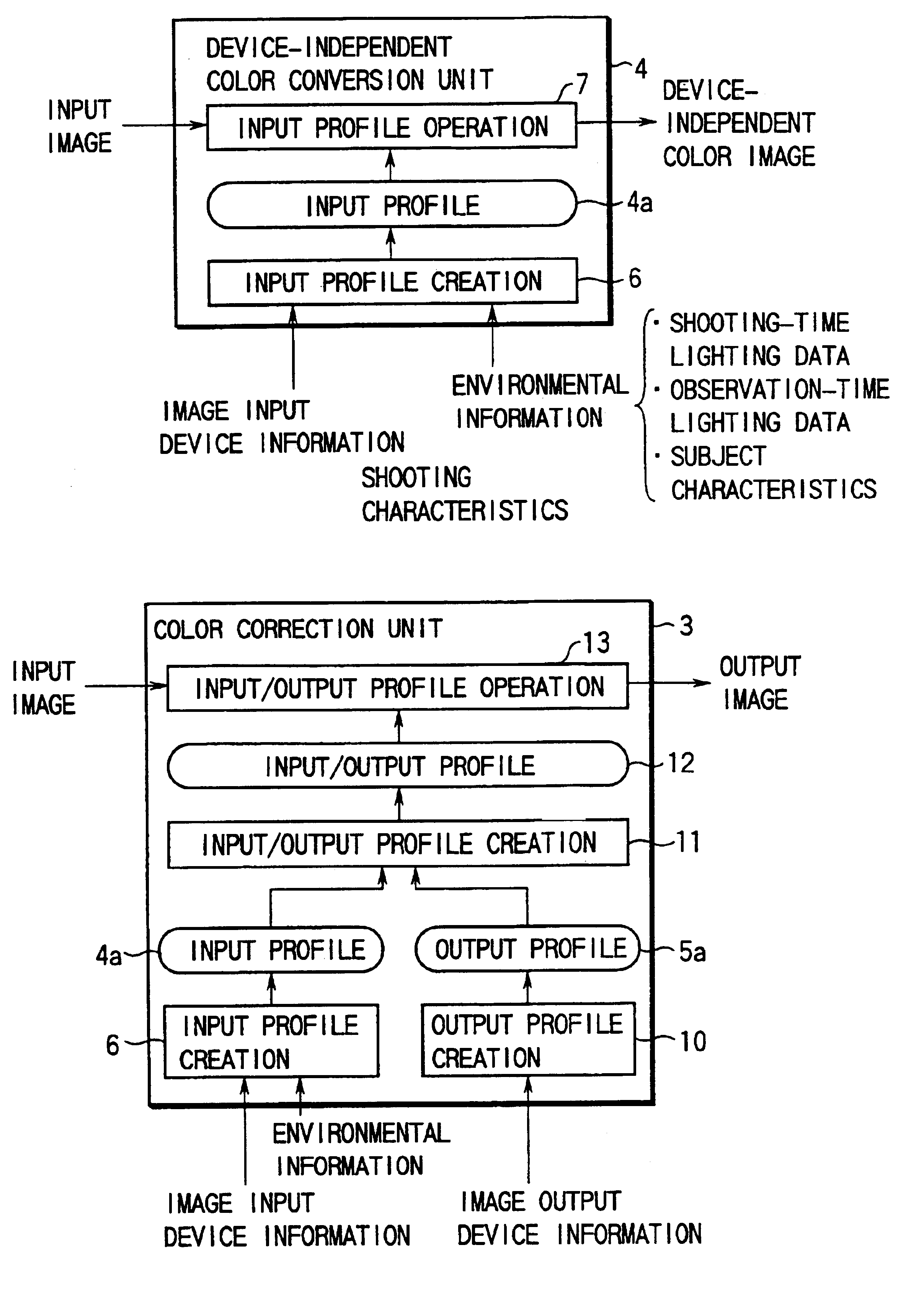
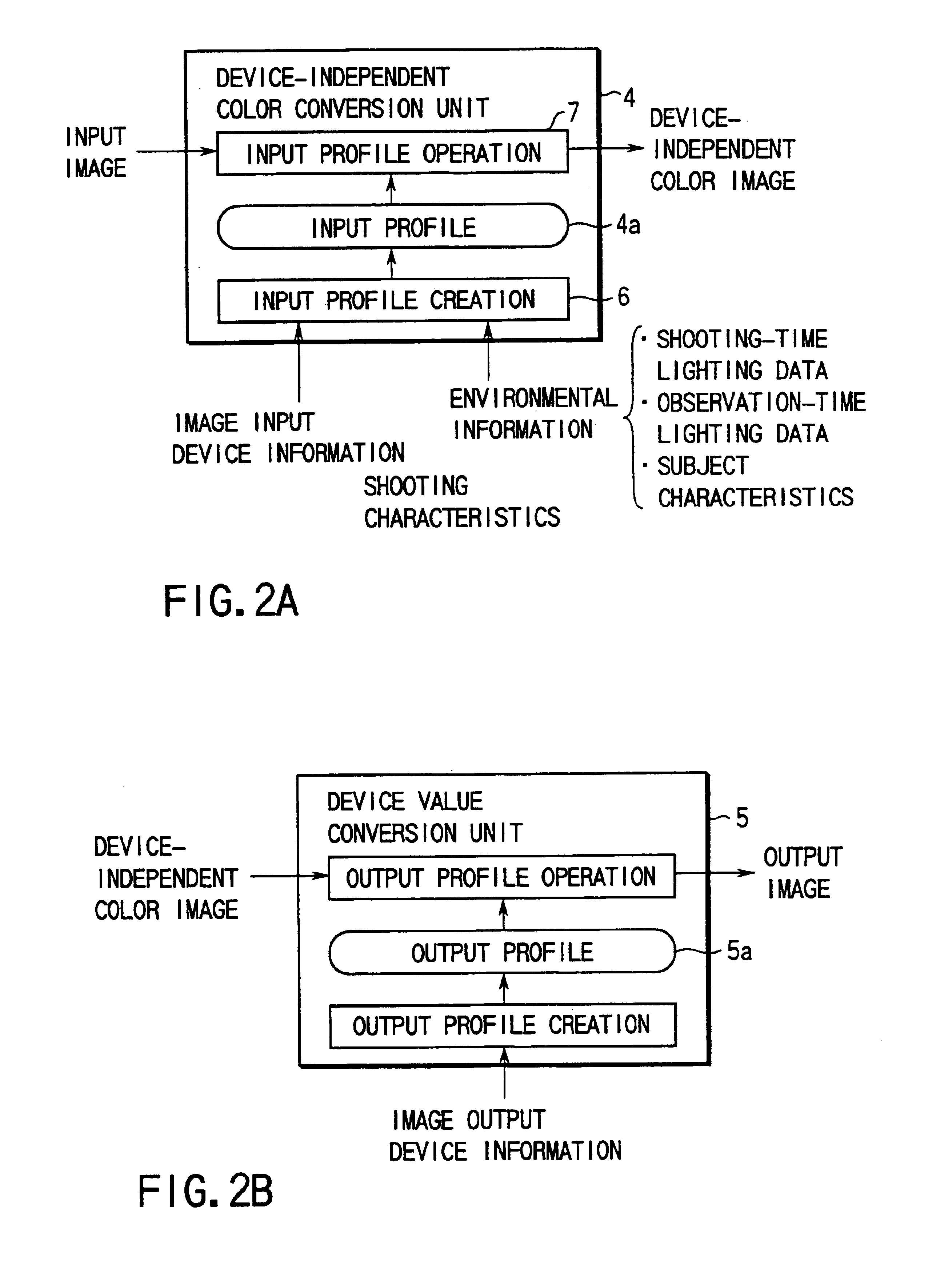
[0075]The device independent color conversion unit 4 converts the colors of an input image to device independent colors by making a reference to an input profile 4a, thereby producing a device independent color image. The device value conversion unit 5 makes a reference to an output profile 5a to convert the device independent color image to an output image that have values that match the characteristics of the image output device 2.

[0076]The device indepe...

second embodiment

[0119]Next, the color reproduction device of the present invention will be described.

[0120]As shown in FIG. 10, the second embodiment is constructed from an image input device 1, a device-independent color conversion unit 4, a device value conversion unit 5, an image output device 2, and an information database 54.

[0121]The device-independent color conversion unit 4 converts the image of a subject shot by the image input device 1 to a device-independent color image by referencing an input profile 4a. The device value conversion unit 5 converts the resulting device-independent color image to device values that suit the characteristics of the image output device 2 by referencing an output profile 5a, thereby producing an output image. The output image is outputted (displayed or printed) by the image output device 2. Such image input device information and environmental information as described previously are entered into the database 54, thus allowing the image input device informatio...

third embodiment

[0123]the color reproduction device of the present invention will be described next with reference to FIGS. 11 and 12.

[0124]In the third embodiment, an input image itself has part of image input device information or environmental information needed to create an input profile, and color conversions are made on image data having a data structure that allows lighting conversion.

[0125]The third embodiment is constructed, as shown in FIG. 11, from an image input device 1, a color correction preprocessing unit 3c, a color correction unit 3d, and an image output device 2.

[0126]Upon receipt of an image of a subject shot by the image input device 1, color correction preprocessing unit 3c combines the input image data and various information necessary for creation of an input profile into an image format that allows color corrections on changes in color due to the effect of lighting, the image format being referred to as the lighting convertible image format. The color correction unit 3d cau...


PUM

PropertyMeasurementUnit
timeaaaaaaaaaa
color conversionaaaaaaaaaa
color reproduction methodaaaaaaaaaa

Abstract

In a color reproduction device, an input profile that is referenced in converting an input image from an image input device into a device-independent color image is created based on image input device information, shooting- and observation-time lighting data, and subject data, allowing accurate conversion of the input image to the device-independent color image. In reproducing the image by an image output device, the spectral reflectance of the subject itself is calculated from image input device information and shooting-time lighting data, thereby reducing the effect of the shooting-time lighting. The colors of the subject under observation lighting are calculated from observation-time lighting data. A color reproduced image is estimated accurately on the basis of the subject data even if the input image has little information.

Description

[0001]This is a division of U.S. patent application Ser. No. 09 / 149,906 filed Sep. 8, 1998 now U.S. Pat. No. 6,466,334.BACKGROUND OF THE INVENTION[0002]The present invention relates to a color reproducing device which transfers accurately the colors of an image of a subject captured by an image input device to an output device.[0003]Various attempts have been made hitherto to print or display colors as they are perceived by the human visual system.[0004]As the performance of computers has been upgraded and their size has been reduced and with the spread of desktop publishing (DTP) systems, color matching techniques have been proposed for matching colors displayed on TV monitors and colors to be printed on printed matter as an object of input and output (for example, U.S. Pat. No. 5,739,928, Japanese Unexamined Patent Publication No. 6-51732, and so on).[0005]A color management system (CMS), which is typical of the color matching techniques, is equipped, as shown in FIGS. 32 and 33, ...

Claims


Application Information

Patent Timeline
Patent Type & Authority Patents(United States)
IPC IPC(8): H04N1/60G01N21/25H04N9/79G06T1/00H04N1/56
CPCH04N1/603H04N1/6086H04N1/6088
Inventor KOMIYA, YASUHIROISHII, KENSUKEOHYAMA, NAGAAKIYAMAGUCHI, MASAHIROOBI, TAKASHI
Owner OLYMPUS CORP
Learn More