
System and method for scanning a region using a low discrepancy sequence

a region scanning and discrepancy sequence technology, applied in the field of data acquisition, can solve the problems of not being generally applicable, unable to confirm and unable to apply to the whole of the factory, and achieve the effect of confirming the accuracy of the calculated location

Inactive Publication Date: 2005-10-25
NATIONAL INSTRUMENTS
View PDF28 Cites 16 Cited by
  • Summary
  • Abstract
  • Description
  • Claims
  • Application Information

AI Technical Summary

Problems solved by technology

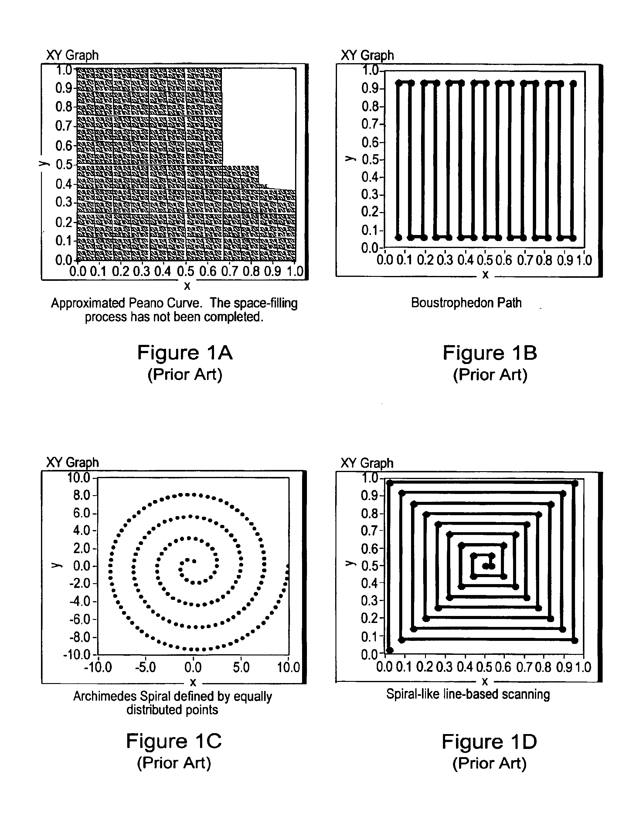
As described below, various prior art scanning schemes may be appropriate for particular applications, but may not be generally applicable due to high curvatures and / or severe start / stop requirements.
Indeed, such structures are generally inappropriate for real scanning scenarios.
Although space-filling is achieved in a very mathematical sense, the curves themselves are unrealizable from a motion control standpoint as they are extremely irregular. FIG. 1A illustrates a space-filling path known as a Peano Curve.
As may be seen, although the Peano Curve fills the space, the complexity and extreme curvature of the path make it a poor solution for motion control applications.
Moreover, accurate space-filling is often neither attainable nor desirable in motion planning.
However, there are significant drawbacks to this scheme.
In particular, the scanning cannot be done continuously because of curvature problems.
Such abrupt changes in motion are problematic for most motion control systems.
The drawbacks of the boustrophedon approach are even more dramatic when searching for small objects of unknown size.
Additionally, this approach clearly lends itself to scanning circular regions, and is therefore unsuitable for non-circular scan regions.
Other drawbacks similar to those of boustrophedon paths also apply to the Archimedes Spiral scheme, such as fixed scanning resolution or path width, which may not be suitable when scanning for small objects.
This scheme, however, suffers from some of the shortcomings of its predecessors.
For example, similar to the boustrophedon approach, there are discontinuities in the path at each corner, leading to sudden accelerations of the scanning apparatus.
Furthermore, the path resolution is fixed, as with the Archimedes Spiral, and may therefore be unsuitable for objects of various or unknown sizes.
This is particularly true when obstacles are part of the environment.
As FIG. 1B demonstrates, such an approach is neither optimal nor acceptable from a motion control standpoint, for at least the reasons given above.

Method used


Image

  • System and method for scanning a region using a low discrepancy sequence
  • System and method for scanning a region using a low discrepancy sequence
  • System and method for scanning a region using a low discrepancy sequence

Examples


example

FIGS. 15A-15C—Surface Scans with Low Discrepancy Curves

[0318]Theorem 4 and Theorem 5 can be used to construct low-discrepancy curves lying on surfaces, various examples of which are given below.

Unit Cube

[0319]Given the surface of a unit cube, FIG. 15A shows a tiling of the whole plane with the following property. Whenever two elements of the tiling have an edge in common the same is true for the corresponding faces of the unit cube. The tiling follows the torus-scheme underlying Theorem 4. According to this theorem almost all α=(α1,α2) generate curves lying on the surface of the unit cube that are low-discrepancy in the sense of Definition 1.

[0320]Note that in the example shown in FIG. 15A, some paths possible on the cube are not possible (with a continuous straight curve) on the tiled surface. For example, faces 3 and 5 of the cube (left) are adjacent, while in the tiled version of the surface (right), they are not. More generally, it may be seen that on the tiled surface, each fac...


PUM


Abstract

A system and method for scanning for an object within a region using a Low Discrepancy Sequence scanning scheme. The system may comprise a computer which includes a CPU and a memory medium which is operable to store one or more programs executable by the CPU to perform the method. The method may: 1) calculate a Low Discrepancy Sequence of points in the region; 2) generate a motion control trajectory from the Low Discrepancy Sequence of points (e.g., by generating a Traveling Salesman Path (TSP) from the Low Discrepancy Sequence of points and then re-sampling the TSP to produce a sequence of motion control points comprising the motion control trajectory); 3) scan the region along the motion control trajectory to determine one or more characteristics of the object in response to the scan. The method may also generate output indicating the one or more characteristics of the object.

Description

PRIORITY CLAIM[0001]This application claims benefit of priority of U.S. provisional application Ser. No. 60 / 266,658 titled “System and Method for Scanning a Region” filed Feb. 5, 2001, whose inventors were Lothar Wenzel, Ram Rajagopal, Dinesh Nair, Joseph Ting and Sundeep Chandhoke.FIELD OF THE INVENTION[0002]The present invention relates to the field of data acquisition, and more particularly to scanning a region.DESCRIPTION OF THE RELATED ART[0003]Many scientific and engineering tasks involve scanning a region, such as an image or object, to acquire data characterizing the region. Examples of such tasks include parts inspection for automated manufacturing systems, alignment tasks for automated assembly systems, and recognition and location tasks in machine vision and motion control systems, among others.[0004]In a typical scanning system a computer system is coupled to a camera which is operable to acquire optical or image information from a target object. The computer system may ...

Claims


Application Information

Patent Timeline
Patent Type & Authority Patents(United States)
IPC IPC(8): G05B19/418G06K9/50G06K9/20G06K9/52G06T7/00G06V10/10G06V10/42
CPCG05B19/41815G06K9/20G06K9/50G06K9/52G06T7/0004G05B2219/32212G05B2219/40554Y02P90/02G06V10/10G06V10/421G06V10/42
Inventor RAJAGOPAL, RAMWENZEL, LOTHARNAIR, DINESH
Owner NATIONAL INSTRUMENTS
Learn More