Gun control system

a control system and gun technology, applied in the field of gun control systems, can solve the problems of difficult to achieve gun system reconfiguration, difficult to change the physical configuration of a ship, and difficult to enhan

Active Publication Date: 2005-10-18
THE UNITED STATES OF AMERICA AS REPRESENTED BY THE SECRETARY OF THE NAVY
View PDF5 Cites 12 Cited by
  • Summary
  • Abstract
  • Description
  • Claims
  • Application Information

AI Technical Summary

Benefits of technology

[0004]A gun control system of the invention includes a fire control kernel and location-independent software components within the fire control kernel. The kernel provides core fire control functionality that is unaffected by changes within the external environment, such as changes to the physical configuration of the gun system of which the gun control system is a part. Each location-independent software component has a specific functionality, and is able to run on any processor within the system in a location-independent manner. That is, the location of the component within the system does not affect its execution, such that it runs in a location-independent manner. Examples of such software components include a target / track management interface software component, a gun control system control interface software component, a gun mount control interface software component, an ownship data interface software component, and a gun control system display interface software component.

Problems solved by technology

Changing the physical configuration of a ship, such as replacing gun mounts, adding or changing sensors, or inserting other enhancements, is thus not an easy enhancement.
Therefore, gun system reconfiguration can be difficult to accomplish.
Reconfiguring these systems in a cost-effective and time-efficient manner may be difficult to accomplish, involving significant time and effort.

Method used


Image

  • Gun control system
  • Gun control system
  • Gun control system

Examples


Embodiment Construction

[0012]In the following detailed description of exemplary embodiments of the invention, reference is made to the accompanying drawings that form a part hereof, and in which is shown by way of illustration specific exemplary embodiments in which the invention may be practiced. These embodiments are described in sufficient detail to enable those skilled in the art to practice the invention. Other embodiments may be utilized, and logical, mechanical, and other changes may be made without departing from the spirit or scope of the present invention. For example, whereas the invention is substantially described in relation to a ship, it is applicable to other types of vehicles as well. The following detailed description is, therefore, not to be taken in a limiting sense, and the scope of the present invention is defined only by the appended claims.

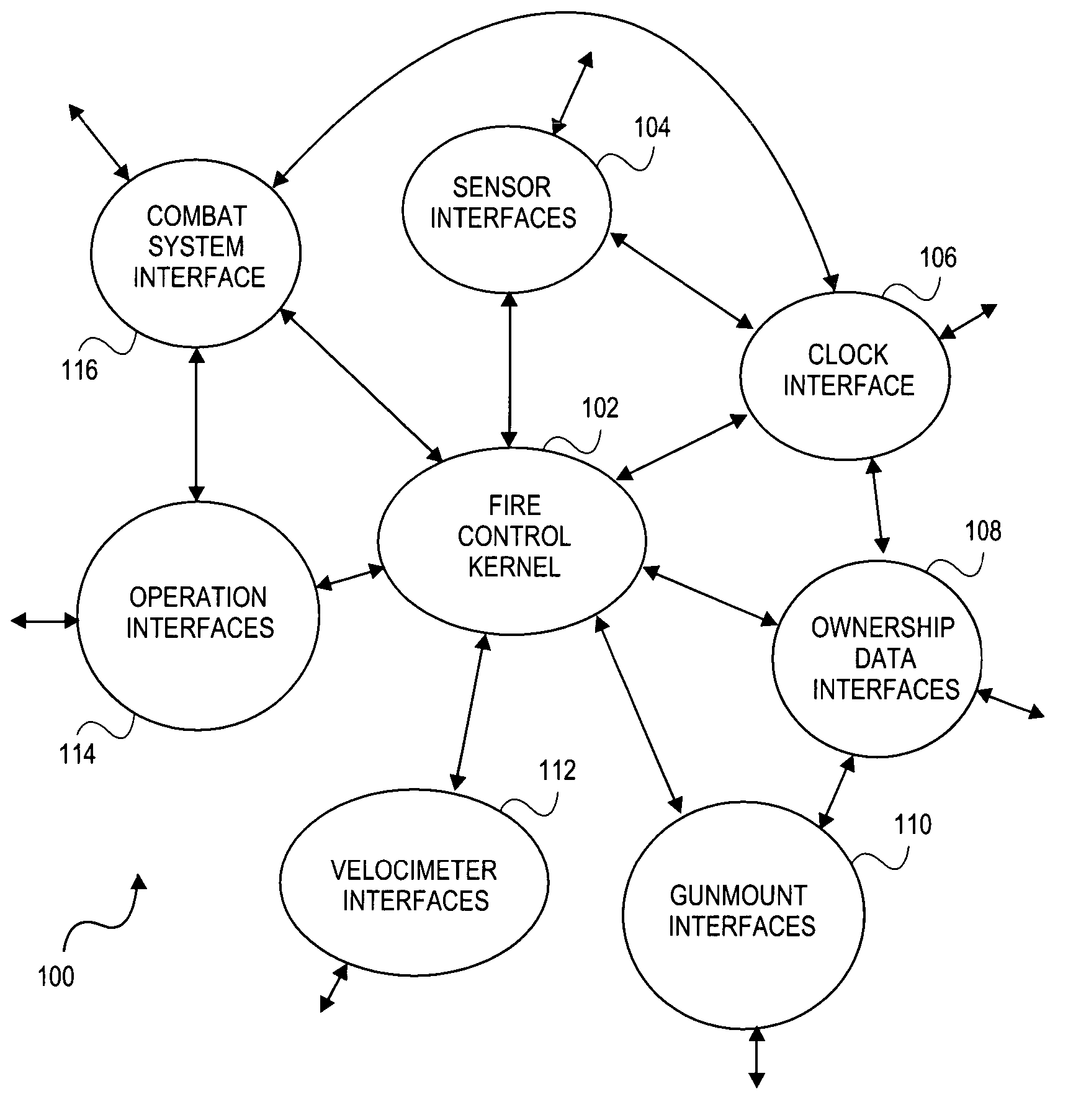
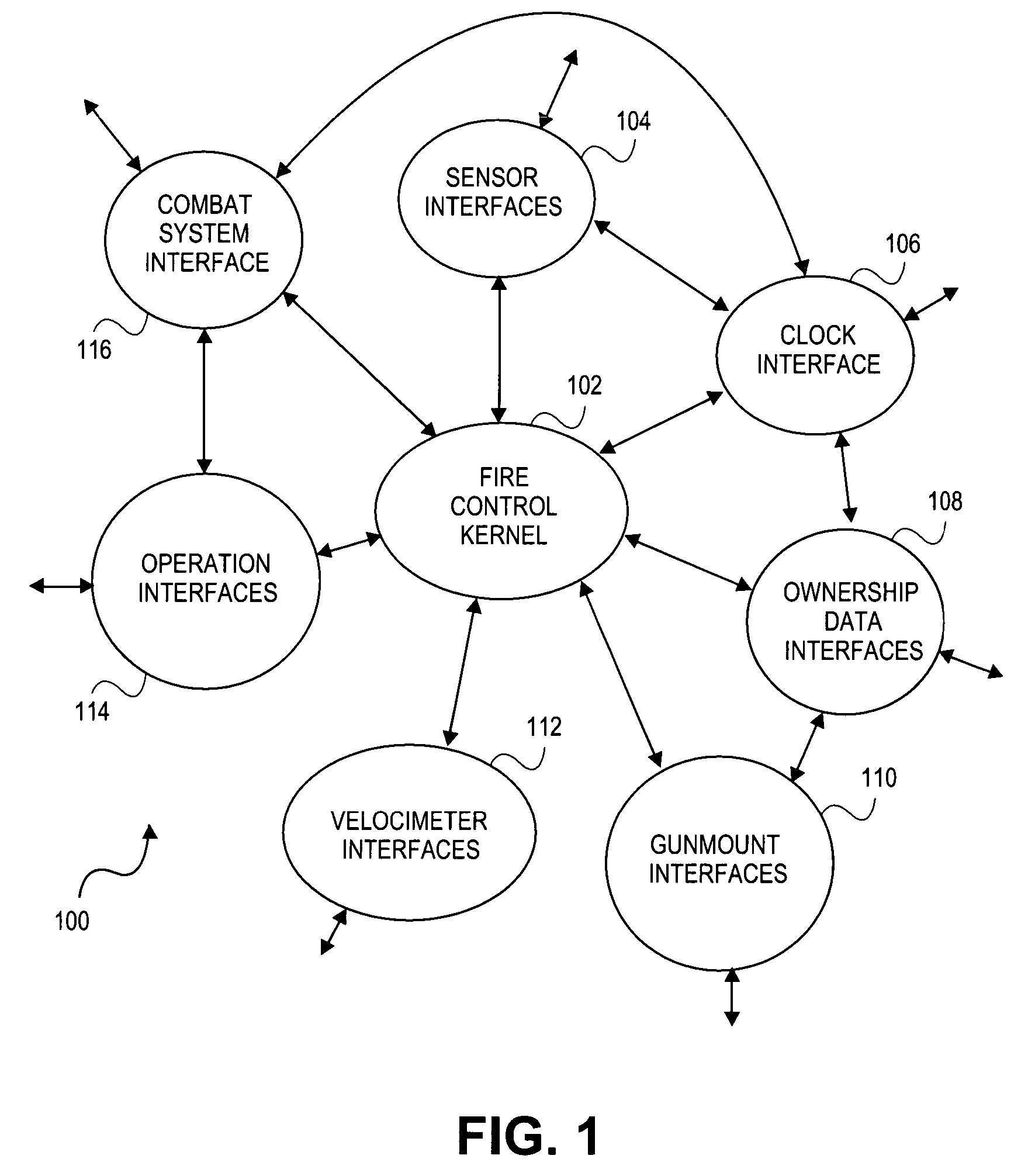
[0013]FIG. 1 shows a gun control system 100, according to an embodiment of the invention. The system 100 is a software system that can be employ...


PUM


Abstract

A gun control system is disclosed that includes a fire control kernel and location-independent software components within the fire control kernel. The kernel provides core fire control functionality that is unaffected by changes within the external environment, such as changes to the physical configuration of the gun system of which the gun control system is a part. Each location-independent software component has a specific functionality, and is able to run on any processor within the system in a location-independent manner. These software components can include a target/track management interface software component, a gun control system control interface software component, a gun mount control interface software component, an ownship data interface software component, and a gun control system display interface software component.

Description

FIELD OF THE INVENTION[0001]The invention relates generally to gunfire systems, and more particularly to gunfire control systems.BACKGROUND OF THE INVENTION[0002]Gun control systems are used to control the guns, or weapons, within vehicles, such as within ships. Traditionally, gun systems are designed so that the gunfire control systems are tightly coupled to the interfaces to the hardware of the system. Changing the physical configuration of a ship, such as replacing gun mounts, adding or changing sensors, or inserting other enhancements, is thus not an easy enhancement. The software design of the gun control system usually has to be changed as well, even though gunfire control has basic, well-understood processing requirements that are typically common to all current gun systems.[0003]Therefore, gun system reconfiguration can be difficult to accomplish. Software engineers may have to be called in to redevelop aspects of the gun control system, to take into account the changes that...

Claims


Application Information

Patent Timeline
Patent Type & Authority Patents(United States)
IPC IPC(8): G06F19/00G06G7/80G06G7/00F41A27/28
CPCF41A27/28F41G5/06F41G5/20
Inventor LUSHER, PAUL W.ROWLAND, HENRY T.
Owner THE UNITED STATES OF AMERICA AS REPRESENTED BY THE SECRETARY OF THE NAVY
Why Eureka
Try Eureka