
Beverage dispensing machine including cartridge ejector assembly

Active Publication Date: 2005-10-18
1693778 ONTARIO LTD
View PDF29 Cites 121 Cited by
  • Summary
  • Abstract
  • Description
  • Claims
  • Application Information

AI Technical Summary

Benefits of technology

[0011]Advantageously, the aspects of the present invention provide a beverage dispensing apparatus with an ejection mechanism for easily ejecting used cartridges from the apparatus by permitting the cartridge holder to slide out from supporting the cartridge. In another aspect, the extractor enters a sidewall of the cartridge, between the filter and the bottom wall of the cartridge. In yet another aspect, the injector pin is designed for spreading the injected flow of liquid causing the spread of liquid through a large volume of the cartridge. In still another aspect, the beverage dispensing machine is designed to inhibit contamination of the extraction and delivery systems and thereby inhibit flavor from one beverage product used during a cycle of the machine, being imparted to beverages brewed during following cycles of the machine.

Problems solved by technology

Existing methods of cartridge ejection can be unreliable.
Additionally, typical beverage dispensing machines of this nature do not have a means to stop a user from retracting the slide mechanism during the operation of the machine.
In the case that a user accidentally pulls the cartridge out of position, the process will be forced to stop mid-cycle.
It is possible that the equipment may become jammed or damaged during this process.
This results in incomplete mixing with the beverage product and inefficient brewing.
In these machines, the extraction and delivery systems can become contaminated with residual beverage product thereby causing flavor from a beverage product used in one cycle of the machine, to be imparted to the beverage brewed during the next cycle of the machine.
In some cases this may be an objectionable or unwanted flavor.

Method used


Image

  • Beverage dispensing machine including cartridge ejector assembly
  • Beverage dispensing machine including cartridge ejector assembly
  • Beverage dispensing machine including cartridge ejector assembly

Examples


Embodiment Construction

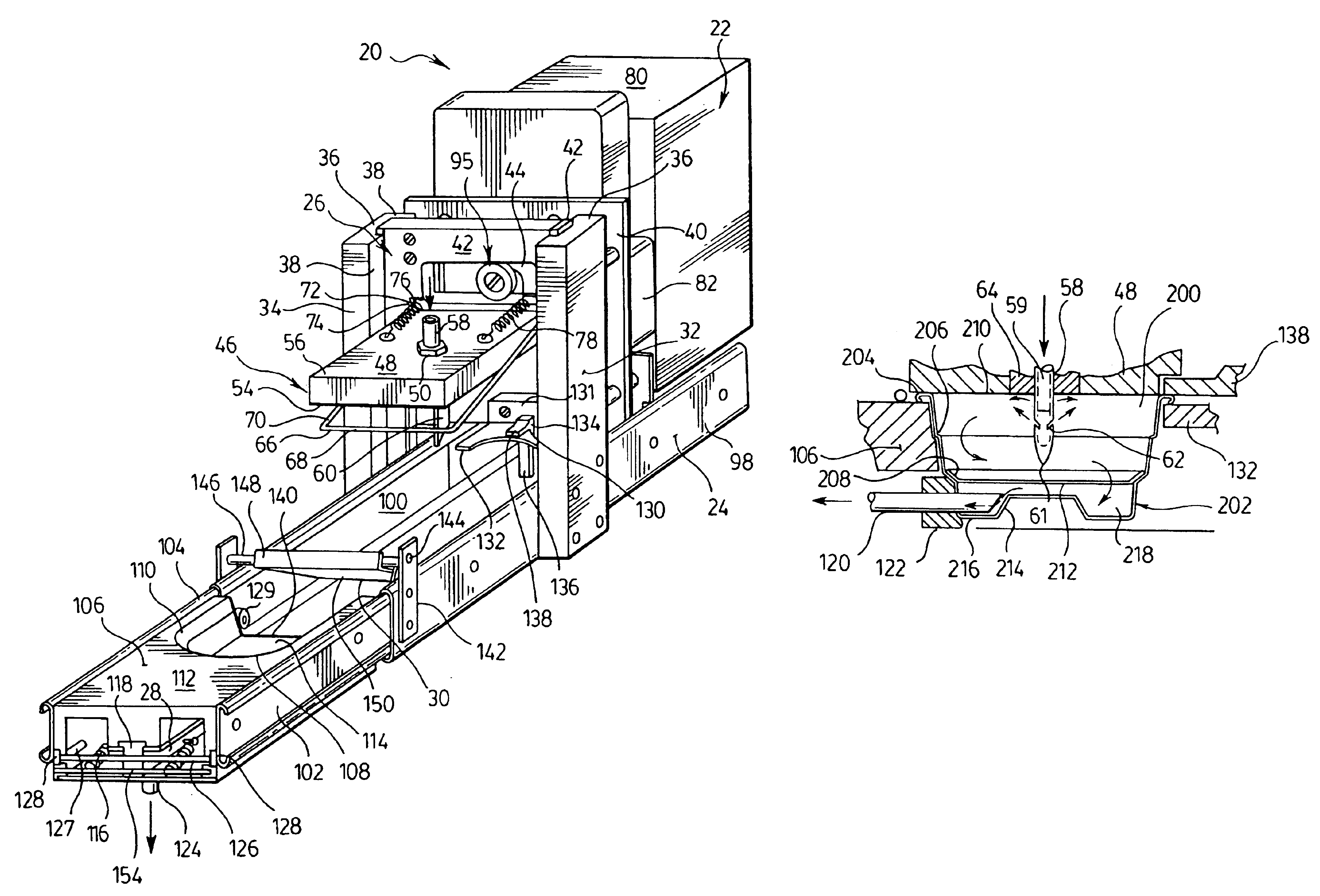
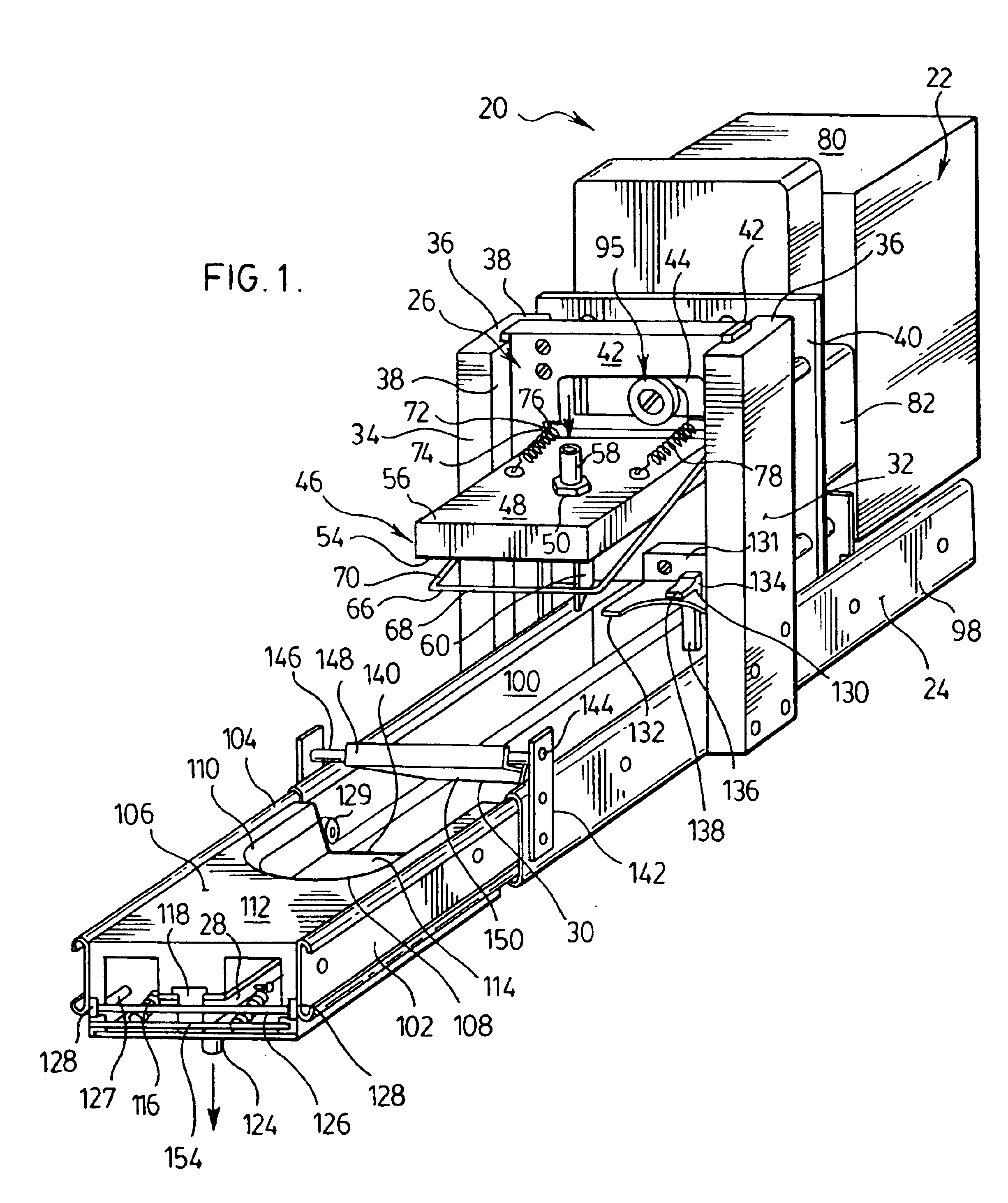
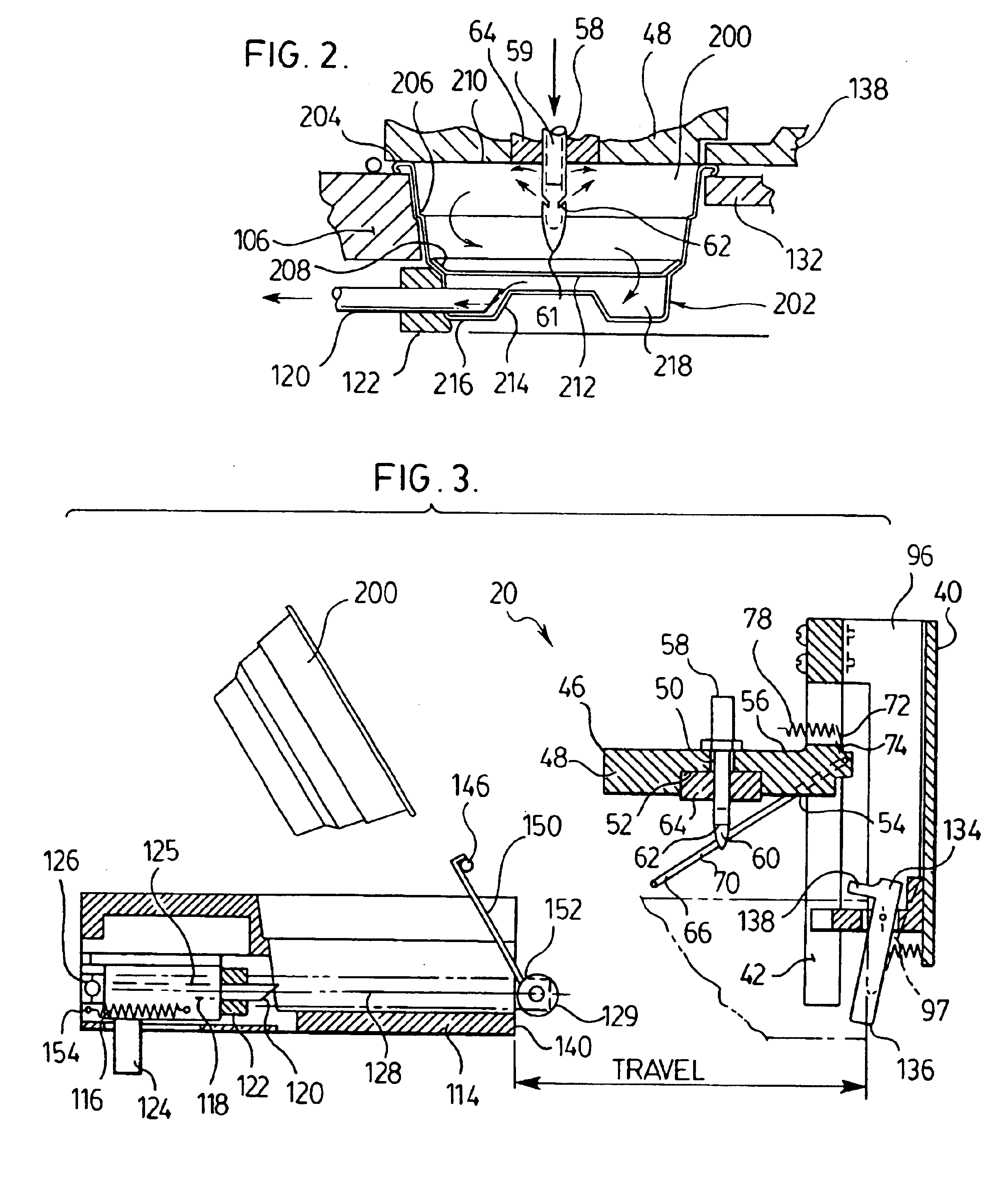
[0021]Referring first to FIG. 1, a beverage dispensing machine is indicated generally by the numeral 20. The beverage dispensing machine 20 generally includes a driving assembly 22 that is mounted in a housing (not shown). A slide assembly 24 is slidable into and out of the housing and moves a beverage cartridge 200 from a loading position shown in FIG. 3 to a loaded position shown in FIG. 4. The driving assembly 22 is mechanically coupled to an injection assembly 26 that is movable into and out of an injection position, shown in FIGS. 4 and 5. In the injection position, the injection assembly 26 interacts with the cartridge 200 to inject water into the cartridge 200 and an extraction mechanism 28 interacts with the cartridge to receive brewed beverage. A cartridge ejector mechanism 30 is also provided to remove the used beverage cartridge 200 from the slide assembly 24.

[0022]Reference is made to FIG. 2 to describe the typical beverage cartridge 200 used with the beverage dispensing...


PUM


Abstract

A beverage dispensing apparatus for extracting beverage from a cartridge includes a slide assembly including a cartridge holder for receiving the cartridge. The slide assembly is used for moving the cartridge holder from a loading position to a loaded position. An injection assembly is coupled to the slide assembly, and includes an injector movable relative to the slide assembly. The injector is movable into and out of an injection position, for piercing the cartridge to inject a liquid into the cartridge. A driving assembly is coupled to the injection assembly for moving the injection assembly into and out of the injection position. An extraction mechanism cooperates with the cartridge holder and includes an extractor that is movable between an extraction position for piercing the cartridge and extracting the beverage, and a non-use position.

Description

FIELD OF THE INVENTION[0001]The present invention relates to beverage dispensing machines, and in particular to a cartridge ejector mechanism for a beverage dispensing machine.BACKGROUND OF THE INVENTION[0002]Single serving beverage dispensing machines are very popular because they provide a fresh tasting beverage quickly without having to produce multiple servings. Single serving beverages such as coffee are typically produced by beverage dispensing machines that use beverage cartridges holding beverage products.[0003]When operating a beverage dispensing machine of this nature, a user typically loads a new cartridge into a cartridge holder located in a slide mechanism and slides the mechanism into place. Once in place, the beverage making process can begin. Generally, a liquid under pressure is injected into the cartridge through the beverage product and the beverage is extracted from the bottom of the cartridge.[0004]Following production of the beverage, the used cartridge must be...

Claims


Application Information

Patent Timeline
IPC IPC(8): A47J31/40A47J31/06A47J31/36A47J31/44
CPCA47J31/0673A47J31/369A47J31/3695A47J31/4467
Inventor HALE, ROBERT
Owner 1693778 ONTARIO LTD
Learn More