Electro-hydraulic actuator with mechanical servo position feedback

a technology of electro-hydraulic actuators and mechanical feedback, which is applied in the direction of fluid-pressure actuators, mechanical devices, servomotors, etc., can solve the problems of difficult to use in practice, relatively expensive type of electro-hydraulic servo valves, and inability to provide electric feedback, etc., to achieve the effect of achieving mechanical feedback from both the first and second stage of a two-stage servo valve with a higher capacity

Inactive Publication Date: 2005-10-18
HONEYWELL INT INC
View PDF24 Cites 10 Cited by
  • Summary
  • Abstract
  • Description
  • Claims
  • Application Information

AI Technical Summary

Benefits of technology

[0012]The present invention, in part, is a recognition that it will be advantageous to implement a simpl...

Problems solved by technology

However, there are applications where accurate electro-hydraulic actuators are required and electrical feedback is not available.
However, the inventor of the present invention has determined that this type of complex electro-hydraulic servovalve is relatively expensive and difficult to utilize in practice.
As aforementioned, attempting to set a higher capacity two-stage servovalve with mechanical feedback such a...

Method used


Image

  • Electro-hydraulic actuator with mechanical servo position feedback
  • Electro-hydraulic actuator with mechanical servo position feedback
  • Electro-hydraulic actuator with mechanical servo position feedback

Examples


Embodiment Construction

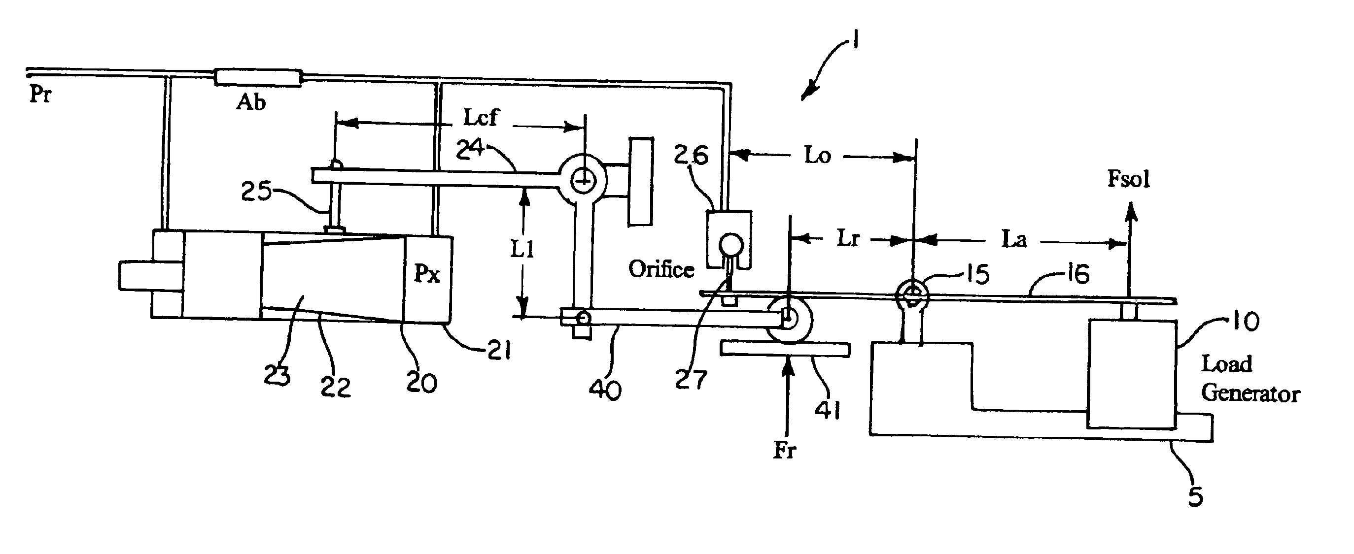
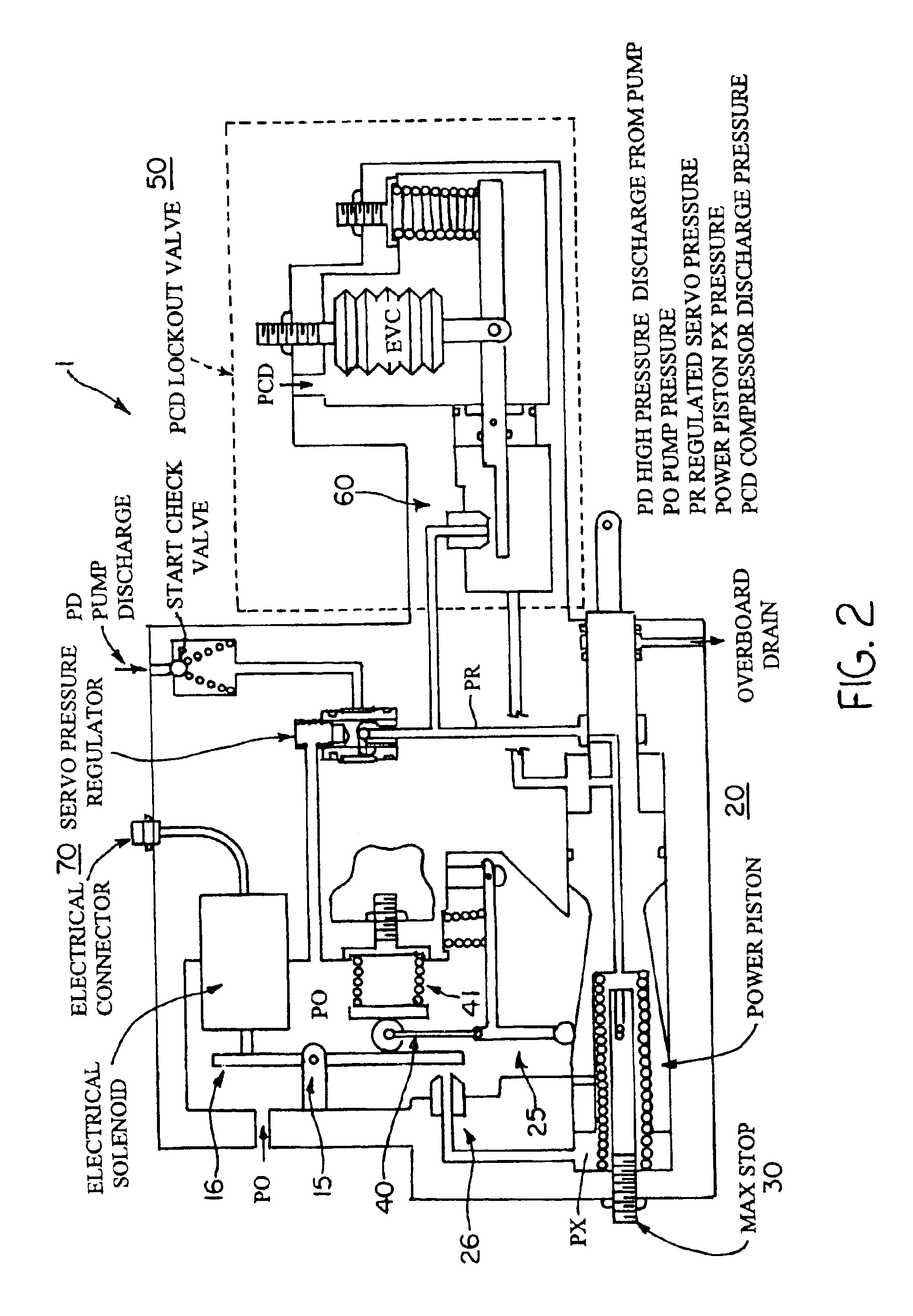
[0020]The present invention will now be described in detail with reference to the accompanying drawings. FIG. 1 is a schematic view of an electro-hydraulic actuator utilizing mechanical servo position feedback according to an embodiment of the present invention. FIG. 2 is a schematic view of an electro-hydraulic actuator utilizing mechanical servo position feedback shown in operation with a high pressure compressor and pump according to an exemplary embodiment of the present invention.

[0021]For many years the Bendix Corporation designed and used computational hydromechanical feedback servomechanism(s) to provide accurate control of subsystems in large gas generator fuel controls. These mechanisms typically sense one or more pneumatic pressures, perform hydromechanical computations, and move an actuator piston to perform some desired function such as positioning a cam or valve in response. The present invention utilizes a similar concept to these types of servomechanisms of the backg...


PUM


Abstract

A method and apparatus for an electro-hydraulic actuator (1) having mechanical feedback provide closed loop control with a high degree of accuracy. The electro-hydraulic actuator (1) includes a current versus load generator (10), a single-stage servomechanism (20, 21, 22, 23), and a device (24, 25, 40, 41) for providing a mechanical feedback force for offsetting an input force (Fsol) of the current versus load generator (10).

Description

TECHNICAL FIELD AND INDUSTRIAL APPLICABILITY OF THE INVENTION[0001]The present invention is generally directed to the field of electro-hydraulic actuators, and more particularly to a method and an apparatus utilizing a highly accurate electro-hydraulic actuator having a force generator to establish closed loop control.BACKGROUND OF THE INVENTION[0002]The inventor of the present invention has determined that there are numerous shortcomings with the methods and apparatus of the background art relating specifically to electro-hydraulic actuators.[0003]Electro-hydraulic actuators that are required to maintain a high level of accuracy are typically controlled with servovalves and use position feedback to achieve closed loop control, e.g., with electrical devices. The position feedback may be accomplished by electrical devices such as LVDTs (Linear Variable Differential Transformer), RVDTs (Rotary Variable Differential Transformer), potentiometers, resolvers, Hall effect sensors, or piezo...

Claims


Application Information

Patent Timeline
IPC IPC(8): F15B9/00F15B9/12
CPCF15B9/12
Inventor DEMERS, DENNIS G.
Owner HONEYWELL INT INC
Why Eureka
Try Eureka