
System and method for surveying underground density distributions

a density distribution and density distribution technology, applied in the field of geophysical surveying, can solve the problems of large amount of computation, difficult problem, and inability to practicably determine variations at smaller scales

Active Publication Date: 2005-10-11
GEDEX
View PDF4 Cites 94 Cited by
  • Summary
  • Abstract
  • Description
  • Claims
  • Application Information

AI Technical Summary

Problems solved by technology

Since satellites typically orbit at altitudes that are several hundred km above the Earth's surface, it is not practically possible to determine variations at smaller scales.
While this is in principle possible, equation (2a) is what is known as an integral equation, and it is generally recognized as being a much more challenging problem.
Although it typically requires a large amount of computation, this is well within the capability of existing computer technology.
There are a number of problems inherent in the approaches that have been attempted to date.
The second problem is related to resolution.
While it is theoretically possible to perform an inversion to any desired resolution, in practice the resolution is limited by the accuracy and resolution of the measured accelerations.
Noise in the measurements will reduce the resolving power of any instrument, requiring a large number of additional measurements and use of statistical techniques in the inversion.
Due to these factors, potential field inversion algorithms in use to date cannot provide a unique inversion because they typically do not properly match the definition of the volume elements to the instrument resolution and do not match the number of independent observations to the number of volume elements.
While other types of data can provide additional constraints to assist in the inversion, fundamentally data of another type, i.e. not directly related to density, are not applicable.
All of the above limitations have limited the success of current approaches to the inversion of gravitational data.

Method used


Image

  • System and method for surveying underground density distributions
  • System and method for surveying underground density distributions
  • System and method for surveying underground density distributions

Examples


Embodiment Construction

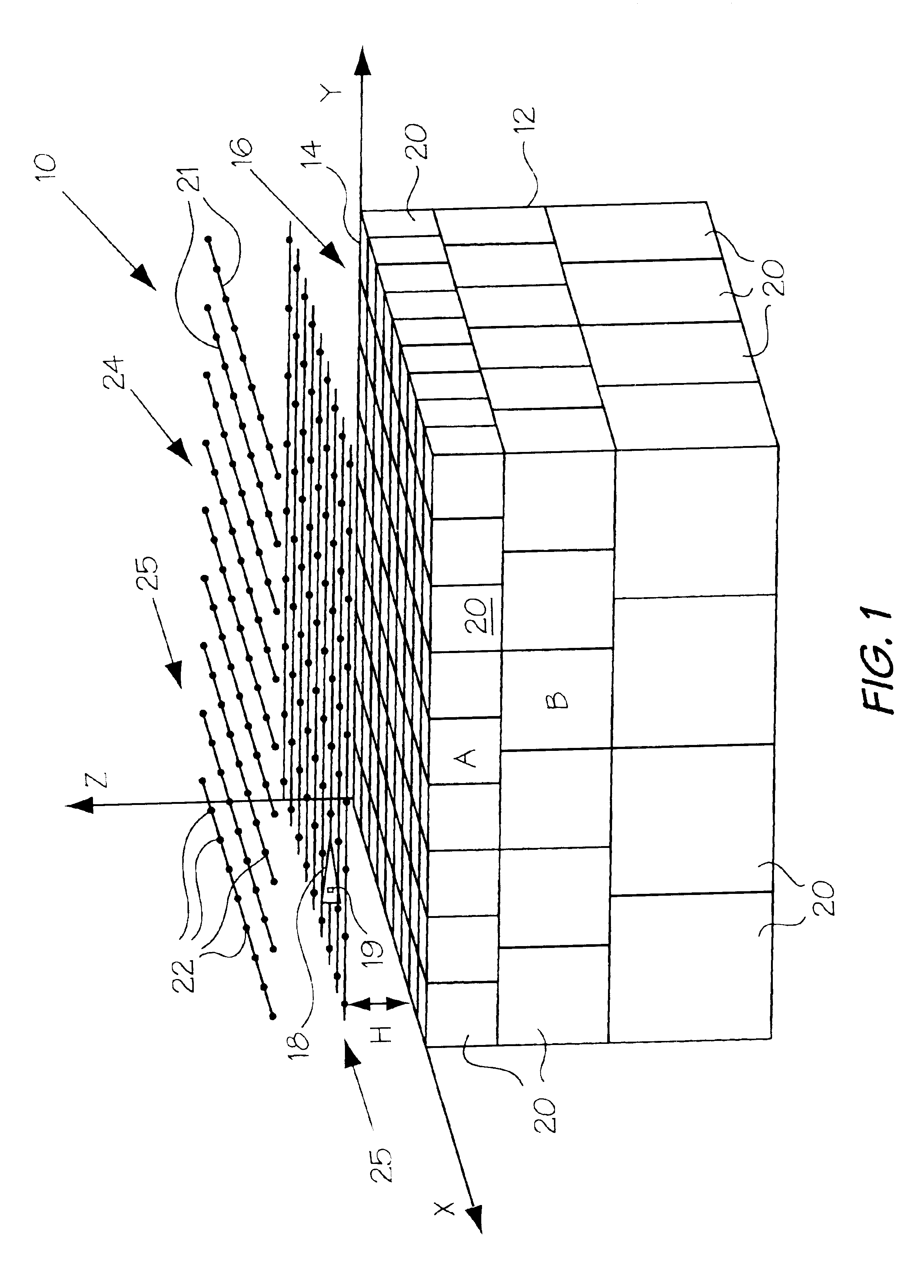
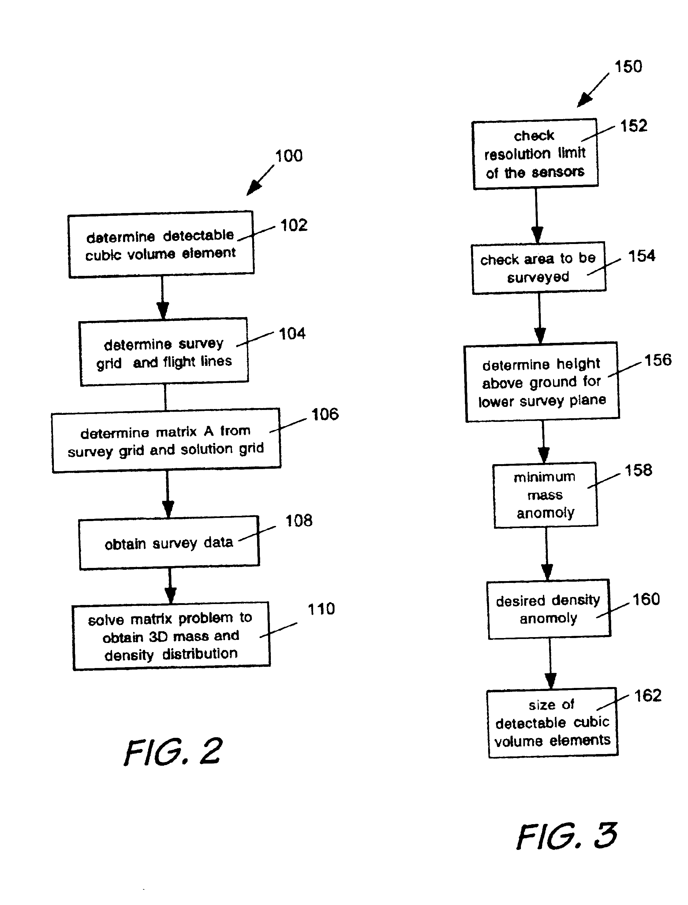
[0048]FIGS. 1 and 2 illustrate a physical survey system 10 (FIG. 1) and the general process steps 100 of the survey method (FIG. 2) of the present invention. The survey method is used to determine the three dimensional density structure of the subsurface material 12 below a survey area 14. Survey vehicles 18 (one shown-FIG. 1) travel over the survey area 14, which overlies a three-dimensional solution volume 16. The three-dimensional density structure of the region within the solution volume 16 is determined from data obtained from gravitational sensors 19 located on a survey vehicle 18 which traverses predetermined flight lines 21. The survey vehicle 18 obtains gravitational data at observation points 22 within a survey grid 24 which typically consists of a plurality of observation planes 25. It should be noted that the area covered by the survey grid 24 should be similar to the survey area 14 overlying the solution volume 16.

[0049]The solution volume 16 shown in FIG. 1 consists of...


PUM


Abstract

A method for geographical surveying includes the steps of determining an observation grid comprising observation points above a solution volume in the ground; making gravitational measurements at the observation points over a survey area; compiling a matrix having elements relating a set of gravitational accelerations and gravity gradient values at the points to the mass values for volume elements in the solution volume; and calculating the three-dimensional density distribution of the volume under the survey area based on the gravitational measurements and the inverse of the matrix. By measuring the magnetic field and gradient at the observation points, the three-dimensional magnetic susceptibility distribution of the volume under the survey area can be determined.

Description

REFERENCE TO RELATED APPLICATIONS[0001]This Application claims benefit from the provisional application No. 60 / 392,025 filed Jun. 28, 2002.FIELD OF THE INVENTION[0002]This invention relates to the field of geophysical surveying, and more particularly to the use of gravitational or magnetic sensors to obtain a three-dimensional picture of subsurface resources below a survey area.BACKGROUND OF THE INVENTION[0003]Gravitational potential is the potential energy associated with a body that has mass. The gravitational potential obeys the principle of superposition: the gravitational potential of a collection of masses is the sum of the gravitational potentials of the individual masses. Therefore a measurement of the gravitational potential field is fundamentally a measure of the composite (additive) contributions from the mass distribution within a detectable range. The gravitational potential at a point near a gravitating body can be measured by observing the acceleration that the potent...

Claims


Application Information

Patent Timeline
Patent Type & Authority Patents(United States)
IPC IPC(8): G01V7/00G01V11/00
CPCG01V7/00G01V11/00
Inventor TRYGGVASON, BJARNI V.
Owner GEDEX
Learn More