Radar apparatus for automobile, attachment direction adjuster and attachment direction adjusting method for radar apparatus

a technology for adjusting devices and radars, applied in the field of radars, can solve the problems of large space requirements, difficult to bear expensive equipment, and difficult to accurately coincide the beam axis with the reference direction,

Inactive Publication Date: 2005-10-11
FUJITSU GENERAL LTD
View PDF16 Cites 18 Cited by
  • Summary
  • Abstract
  • Description
  • Claims
  • Application Information

AI Technical Summary

Benefits of technology

[0009]Accordingly, the invention provides a radar apparatus for an automobile, and an attachment direction adjuster and an attachment direction adjusting method for the radar apparatus, which can adjust a search direction in a simple manner at a low cost.
[0011]As described above, when the radar apparatus is attached to the vehicle, it is necessary to adjust deviation of the beam axis. When the radar apparatus of the first aspect is attached to a vehicle, an attachment-direction adjustor is placed on one of the correction surfaces and the reference surface, which is indicated by the selection indication and the posture of the radar apparatus is adjusted. As a result, the deviation of the beam axis can be corrected and the functional portion can perform searching in a predetermined direction with respect to the vehicle. There is no need to adjust an attachment direction of the radar apparatus while directly measuring a searching direction of the functional portion. Therefore, it becomes possible to adjust the attachment direction of the radar apparatus easily at low cost.
[0013]According to a third aspect of the invention, in the radar apparatus of the second aspect, angles between the correction surfaces and the attachment surface are different from each other. Since the angles are different from each other, the adjustment direction of the radar apparatus can be adjusted easily in various situations.
[0016]According to a sixth aspect of the invention, in the radar apparatus of the first aspect, the casing is formed with the correction member integrally. The sixth aspect of the invention can prevent a user from losing the correction member.
[0017]According to a seventh aspect of the invention, in the radar apparatus of the first aspect, the selection indication is a predetermined color, which is coated on the one of the correction surfaces. Since the correction surface to be used is coated with the predetermined color, a user can find the correction surface to be used easily.

Problems solved by technology

However, it is necessary to dispose an antenna for the adjustment, and further since the predetermined position is required to be several tens meters away from the vehicle body, a large space is required.
In the case of performing the attachment of the radar apparatus for an automobile in a dealer for selling automobiles or are pair shop for performing the maintenance of automobiles, an adjustment equipment such as the antennal or the reflection member which requires to secure a large space is an expensive equipment difficult to bear.
However, at the time of assembling the radar apparatus for an automobile into the body, it is difficult to coincide the beam axis accurately with the reference direction, which is determined based on the casing.
If the accuracy of the mechanical portion were improved, there would arise problems that a cost of the apparatus raises due to the increase of the processing number such as work and the outer size of the casing becomes large.

Method used


Image

  • Radar apparatus for automobile, attachment direction adjuster and attachment direction adjusting method for radar apparatus
  • Radar apparatus for automobile, attachment direction adjuster and attachment direction adjusting method for radar apparatus
  • Radar apparatus for automobile, attachment direction adjuster and attachment direction adjusting method for radar apparatus

Examples


Embodiment Construction

[0034]The embodiments of the invention will be explained with reference to the accompanying drawings. In the figures, portions corresponding to those having been explained are referred to by the common symbols, with explanation thereof being omitted.

[0035]FIG. 1A shows the schematic configuration of a radar apparatus 1 for an automobile according to an embodiment of the invention. FIG. 1B shows an attachment state thereof.

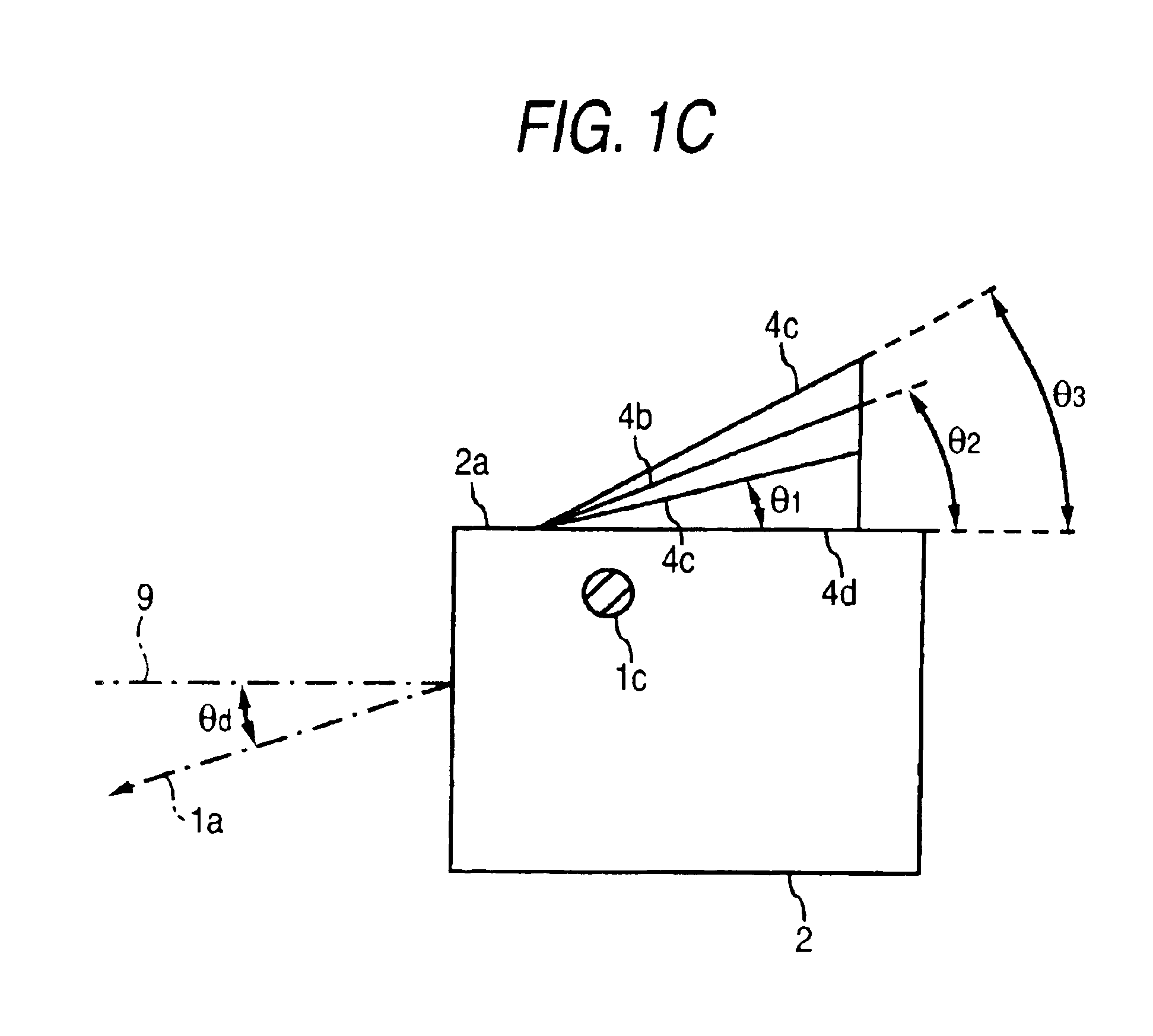
[0036]As shown in FIG. 1A, the radar apparatus 1 for an automobile according to the embodiment makes a radio wave of a millimeter wave band, for example, narrow in a beam shape, then irradiates the radio wave as a search beam 1b in a direction along a beam axis 1a, and receives a reflection wave reflected by a target such as an object existing in a beam radiation area to detect the position of the target, the distance to the target or the like. As the search beam, not only the radio wave but also other waves such as electromagnetic wave including light such as lase...


PUM


Abstract

A radar apparatus for a vehicle includes a casing, a correction member, and a selection indication. The casing includes a functional portion, which performs searching, and a reference surface. The correction member includes a plurality of correction surfaces. The selection indication indicates which one of the correction surfaces and the reference surface an attachment-direction adjustor is to be placed on during an attachment operation of the radar apparatus to the vehicle.

Description

BACKGROUND OF THE INVENTION[0001]1. Field of the Invention[0002]The present invention relates to a radar apparatus for an automobile attached to the body of the automobile, and an attachment direction adjuster and an attachment direction adjusting method for the radar apparatus.[0003]2. Description of the Related Art[0004]Conventionally, such a technique has been developed that a radar apparatus utilizing a radio wave or a laser beam is mounted on the body of an automobile thereby to search other vehicles etc. on a road on which the automobile runs (for example, see JP-A-Sho. 59-37471 and JP-A-Hei. 1-197684). In order to perform accurate search, it is necessary to make a searching range utilizing a radio wave or a laser beam narrow in a beam shape. When the search range is made narrow, at the time of attaching the radar apparatus for an automobile to the body of the automobile, it is required to adjust the radar apparatus so as not to deviate a beam axis in the vertical direction. W...

Claims


Application Information

Patent Timeline
IPC IPC(8): G01S7/40G01S13/93
CPCG01S7/4026G01S7/4972G01S2007/4034G01S2007/403G01S7/403G01S7/4034
Inventor ISAJI, OSAMUKAJIOKA, HIDEKIHATANAKA, NORIHIKO
Owner FUJITSU GENERAL LTD
Why Eureka
Try Eureka