
Apparatus for monitoring electric motor screw driver system

a technology of screw driver and apparatus, which is applied in the direction of motor/generator/converter stopper, dynamo-electric converter control, instruments, etc., can solve the problem that the conventional electric motor does not have any function to monitor the condition of fastening operation, and achieve the effect of increasing the efficiency of assembly process

Inactive Publication Date: 2005-10-11
SEHAN ELECTOOLS
View PDF15 Cites 58 Cited by
  • Summary
  • Abstract
  • Description
  • Claims
  • Application Information

AI Technical Summary

Benefits of technology

[0008]It is, therefore, an object of the present invention to provide an electric motor screw driver system for monitoring a fastening operation in order to increase efficiency of assembling processes.

Problems solved by technology

However, the conventional electric motor does not have any functions to monitor conditions of fastening operation such as the number of fasteners which are completely fastened or malfunctioning fastening operation.

Method used


Image

  • Apparatus for monitoring electric motor screw driver system
  • Apparatus for monitoring electric motor screw driver system
  • Apparatus for monitoring electric motor screw driver system

Examples


Embodiment Construction

[0022]Other objects and aspects of the invention will become apparent from the following description of the embodiments with reference to the accompanying drawings, which is set forth hereinafter.

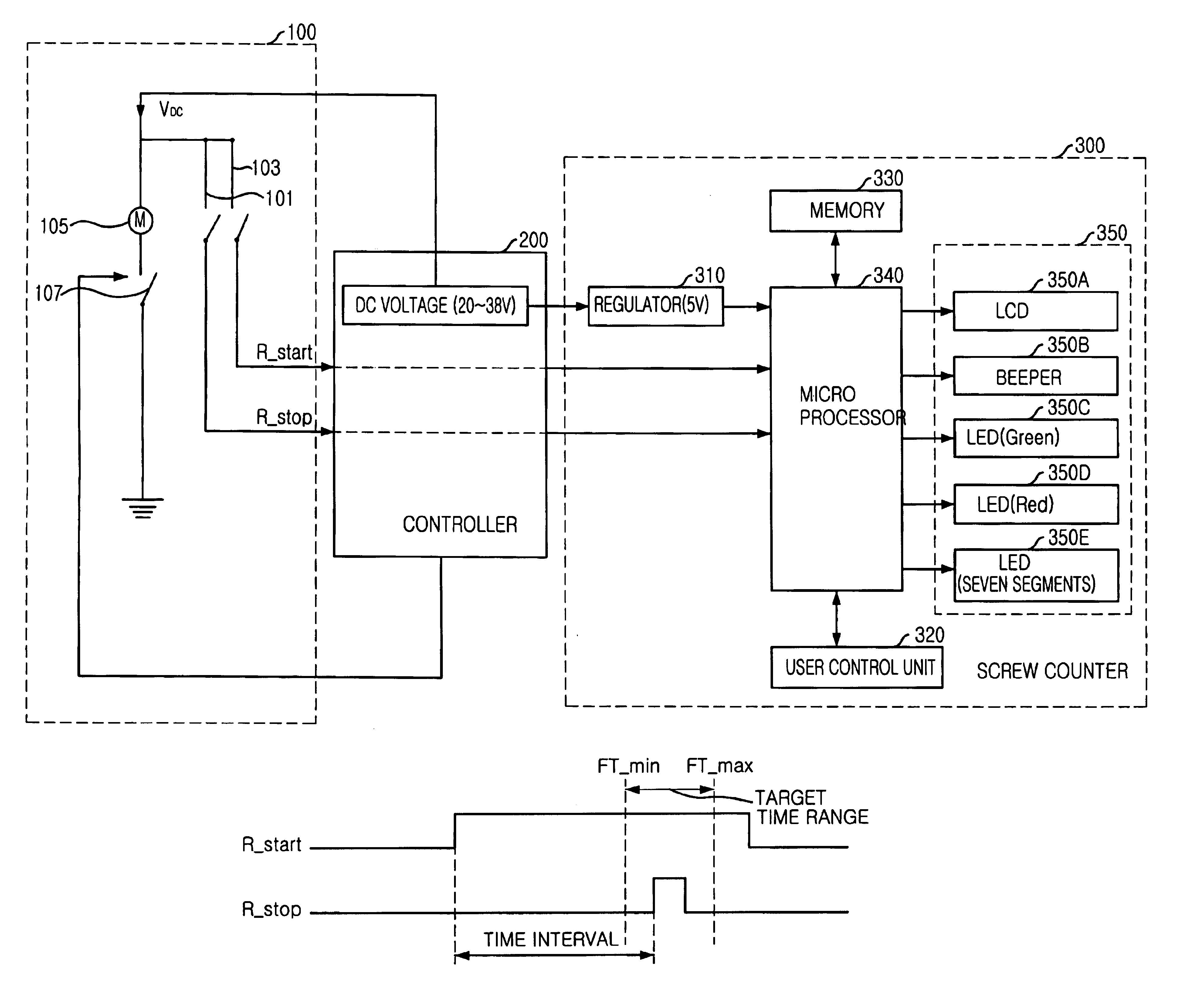
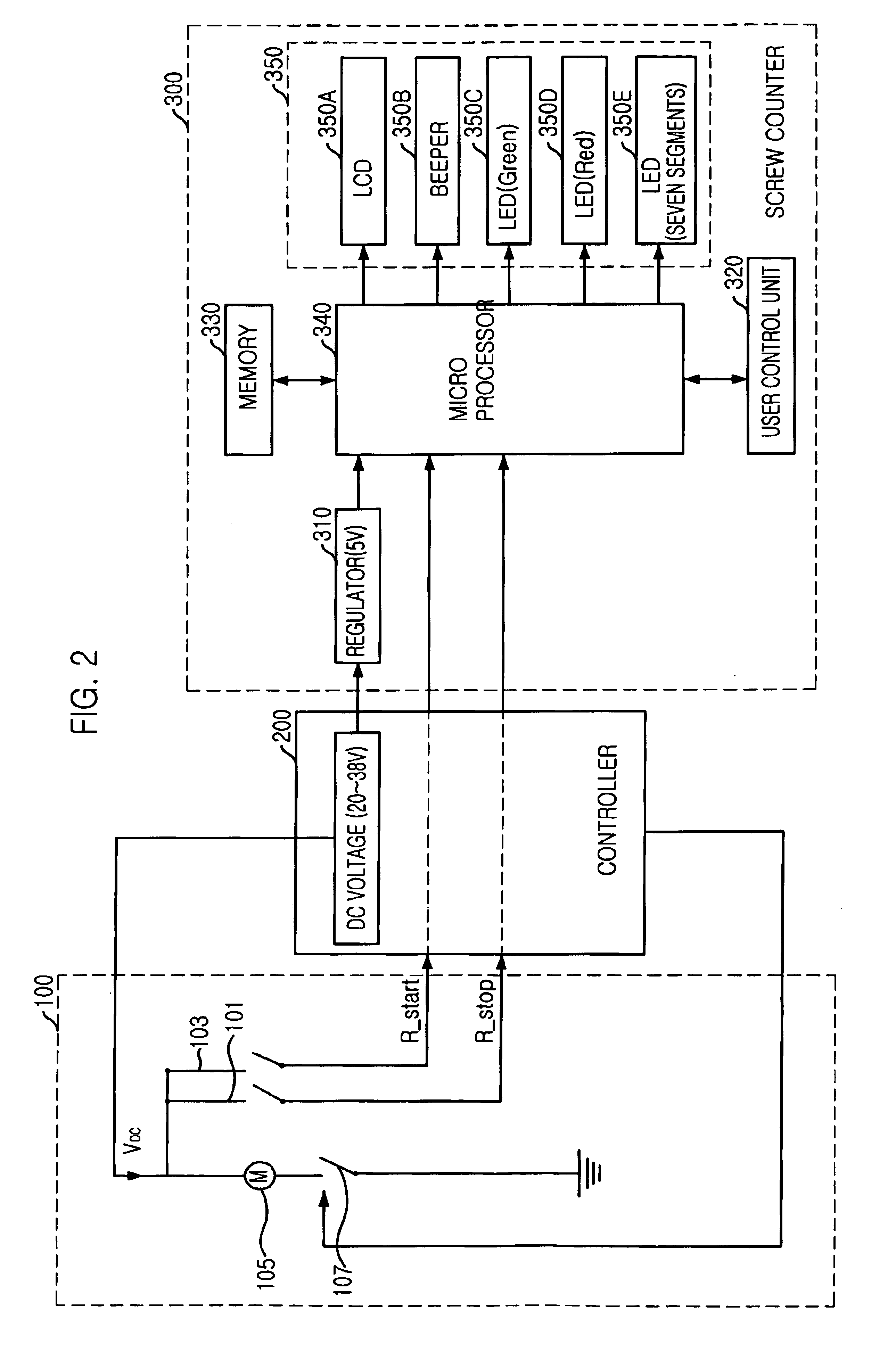
[0023]FIG. 2 is a diagram for illustrating an electric motor screw driver system in accordance with a preferred embodiment of the present invention.

[0024]Referring to the FIG. 2, the electric motor screw driver includes a driver 100, a controller 200 for controlling operations of the driver 100, and a driver monitor 300 for verifying or determining whether a fastening operation of the driver is appropriately completed or not based on a rotation start signal and a rotation stop signal from the driver and outputting a result of determination by generating information signal.

[0025]The driver 100 includes a first switching unit 103 for generating a rotation start signal in order to rotate a rotary axis of the driver 100 and a second switching unit 101 for generating a rotation stop signal in or...


PUM

PropertyMeasurementUnit
Timeaaaaaaaaaa

Abstract

A driver monitor for a driver system. A driver monitor includes a driver monitoring unit for monitoring the fastening operation of the driver based on pre-determined fastening information. A rotation start signal and a rotation stop signal are used to determine whether the fastening operation is appropriately completed or not. An information signal is generated based on a result of monitoring. An operation processing unit outputs the result information signal from the driver monitoring unit to external peripheral apparatus and receives an operation information signal from the external peripheral apparatus in order to cooperate with the external peripheral apparatus. A display unit receives the information signal from the driver monitoring unit and displays the information signal.

Description

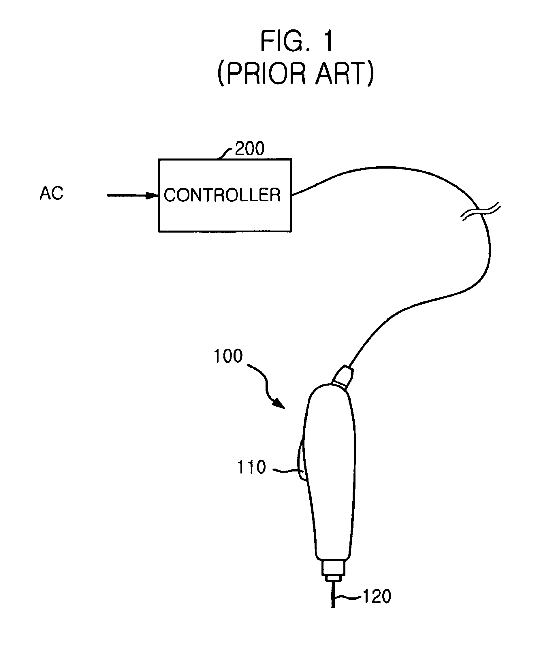
FIELD OF THE INVENTION[0001]The present invention relates to an electric motor screw driver system; and, more particularly, to an apparatus for monitoring fastening operation of the electric motor screw driver system in order to increase efficiency of assembling processes.DESCRIPTION OF RELATED ARTS[0002]It is well known that a conventional electric-motor screw driver performs to fasten various fasteners such as a screw, a bolt or nuts by controlling a rotary axis of the electric-motor screw driver in response to a torque of electric power used for rotating the rotary axis.[0003]FIG. 1 is a diagram for illustrating a conventional electric-motor screw driver. Referring to FIG. 1, the conventional electric-motor screw driver includes a driver 100 and a controller 200. The driver 100 also includes a lever 110.[0004]When the lever 110 is pushed, the driver 100 sends an activation signal, which is logical high, to the controller 200 and the controller 200 drives an electric motor equippe...

Claims


Application Information

Patent Timeline
IPC IPC(8): B25B23/14H02P1/00H02P1/04H02P3/00B23P19/06B25B21/00B25B23/147B25B23/00
CPCB23P19/066B25B21/00B25B23/147Y10T29/53057Y10S388/937Y10T29/5303B25B23/00
Inventor CHO, YONG KI
Owner SEHAN ELECTOOLS
Learn More