
Apparatus for inputting coordinates

a technology of coordinates and optical type, applied in the field of optical type apparatus for inputting coordinates, can solve the problems of reducing the detection accuracy of a specific area of the coordinate, unnecessary brush script, and prior art, and achieve the effects of improving visibility, detecting the coordinate accurately, and being convenient to opera

Inactive Publication Date: 2005-10-04
RICOH KK
View PDF11 Cites 19 Cited by
  • Summary
  • Abstract
  • Description
  • Claims
  • Application Information

AI Technical Summary

Benefits of technology

The present invention provides an apparatus for inputting coordinates that is easy to operate, can accurately detect coordinates, and improve visibility. The apparatus includes an optical unit integrated with a light source and a light receiving section, which reduces the projection of the optical unit and allows for adjustable height of the light emitted from the light source and the reflecting section. Additionally, the apparatus can be coupled with another apparatus for inputting coordinates and includes a shielding plate to adjust the height of the emitted light.

Problems solved by technology

However, the prior art has the following problems.
Moreover, the conventional apparatus for inputting coordinates has the following problem that a detection accuracy is reduced in a specific area on the coordinate.
If the light irradiated from the optical unit 1302 is far from the coordinate input plane 1101, there is a problem that “unnecessary brush script” (called as “hane” in calligraphy serif” or “faintness” occurs in a locus drawn by the pointing means displayed on a display screen.
For this reason, there is a problem that a visibility becomes worse because the reflecting plate or the shielding plate on a joined portion becomes an obstacle depending upon viewing positions.
More specifically, following problem arises when a plurality of apparatuses for inputting coordinates are used.
For example, at a conference hall, in the case of attending a lecture from various positions, the reflecting plate or the shielding plate becomes an obstacle from listeners who are positioned at a low angle with respect to the coordinate input plane; for this reason, the visibility becomes worse.

Method used


Image

  • Apparatus for inputting coordinates
  • Apparatus for inputting coordinates
  • Apparatus for inputting coordinates

Examples


Embodiment Construction

[0038]Preferred embodiments of the present invention will be described below with reference to the accompanying drawings.

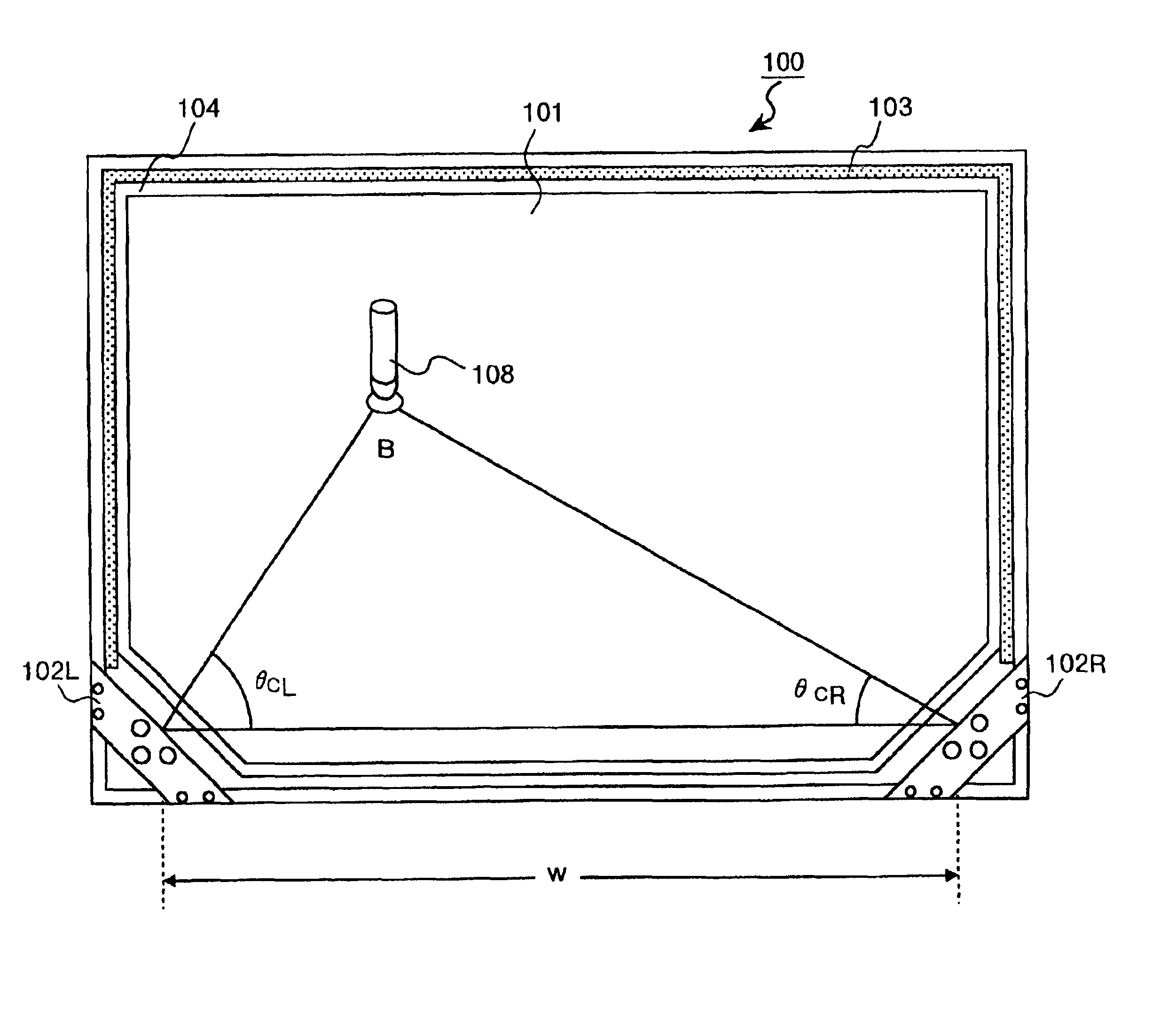
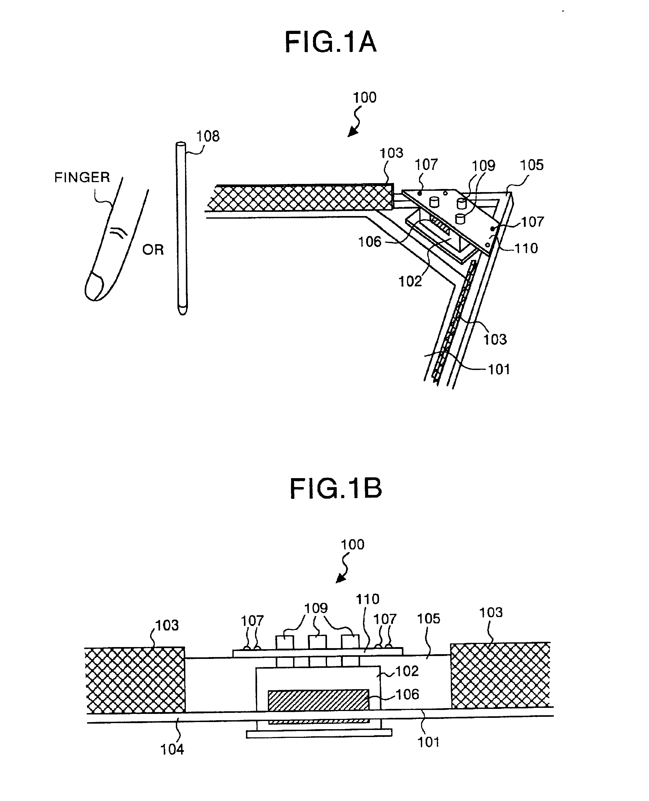
[0039]FIG. 1A and FIG. 1B are views schematically showing a corner portion including an optical unit of an apparatus for inputting coordinates of the present invention. FIG. 1A is a perspective view showing the apparatus for inputting coordinates, and FIG. 1B is a front view when viewing the optical unit from a light emitting plane. A corner cube reflector is given as one example of the above member. A apparatus for inputting coordinates 100 is composed of a coordinate input plane 101 for inputting a coordinate position, an optical unit 102, a reflecting section 103, a support plate 104 for fixing the coordinate input plane 101, and a frame section 105 for reinforcing the support plate 104 and fixing the reflecting section 103. More specifically, the optical unit 102 has a light emitting section which emits light that is substantially parallel to the coordinate in...


PUM


Abstract

The apparatus for inputting coordinates has a support plate including a coordinate input plane for inputting a coordinate position, an optical unit is formed by integrating a light source and a light receiver. The light source emits light which is substantially parallel to the coordinate input plane. A reflecting section reflects the light emitted from the light source. The optical unit is embedded in the coordinate input plate by the use of a frame, an optical unit retaining plate and a screw.

Description

FIELD OF THE INVENTION[0001]The present invention in general relates to an apparatus for inputting coordinates. More particularly, this invention relates to an optical type apparatus for inputting coordinates which determines coordinates of a position by detecting a direction in which an emitted light is shielded or reflected.BACKGROUND OF THE INVENTION[0002]A conventional optical type apparatus for inputting coordinates includes an optical unit which is constructed in such a manner that a light emitting section and a light receiving section are integrally formed. The apparatus for inputting coordinates determines the coordinates of a position by sensing shielding of light due to a pointing means such as a stick, finger or the like, or by sensing light reflected by a reflecting member attached to the pointing stick.[0003]FIG. 12A and FIG. 12B schematically shows a corner portion including the optical unit of a conventional apparatus for inputting coordinates. FIG. 12A is a perspecti...

Claims


Application Information

Patent Timeline
Patent Type & Authority Patents(United States)
IPC IPC(8): G06F3/033G01B11/00G06F3/042
CPCG06F3/0421G06F3/0423
Inventor HIRABAYASHI, TAKESHI
Owner RICOH KK
Learn More