
Electric razor inner blade unit

a technology of electric razors and inner blades, which is applied in the direction of metal working devices, etc., can solve the problems of requiring a lot of shaving time, and achieve the effect of reducing the strok

Inactive Publication Date: 2005-10-04
MATSUSHITA ELECTRIC WORKS LTD
View PDF19 Cites 10 Cited by
  • Summary
  • Abstract
  • Description
  • Claims
  • Application Information

AI Technical Summary

Benefits of technology

[0003]The present invention has been achieved in view of the above problem to provide an inner cutter for the dry shaver which is capable of cutting the hairs without bending them by the inner cutter irrespective of the conditions of the hairs introduced through the apertures of the outer cutter, and therefore making the close shave at a reduced stroke.
[0004]The inner cutter for a dry shaver in accordance with a present invention includes a plurality of blades 30 which are supported on a base 20 and are driven to move relative to an outer cutter 10 in hair shearing engagement with the outer cutter for cutting the hairs. The blades are arranged in parallel with each other and are each provided on opposite sides at the upper end thereof with cutting edges 32. The cutting edge is defined by a top face of the blade and a rake face 33 formed on the underside of the blade. The rake face 33 is inclined with respect to the top face at an angle of α (°). The cutting edge is rounded at its tip to have a radius of curvature R (μm) which satisfies a relation that R≦−0.067·α+4.7. With this arrangement, it is possible to lower cutting resistance at the time of cutting hairs below a load required to bend the hairs. Whereby the hair introduced in any portion of the hair introducing aperture can be cut only by the action of the blade of the inner cutter without being bent, which brings about a flat cutting plane at the section of the hair and therefore enables a close shave at a small number of shaving strokes.
[0005]Preferably, each of the blades 30 includes a rib 34 which projects on the underside of the blade such that the cutting edges 32 project sideward from an upper end of the rib 34 by an amount of at least 0.05 mm. By provision of the rib 34 on the underside of the blade 30, and taking into account that the hair has normally a diameter of 0.1 mm, the cutting edge can be made to have a projection length, one-half or more of the hair's diameter. Accordingly, until the cutting edge 32 cuts the hair by ½ or more of its diameter, the portion other than the cutting edge can be kept away from the hair and does not act to bend the hair. Thus, the cutting edge can cut the hair without bending the same, assuring to cut the hair successfully.
[0006]It is preferred that each blade 30 is formed in its top face with a recess 38 or projection 39 extending along a length of the blade. The recess or projection can reduce a shearing contact area with the outer cutter, thereby reducing shearing load and the associated temperature increase.
[0007]Further, each blade is formed on its rake face 33 with a hardened layer 35 that is responsible for elongating sharpness life of the cutting edge.

Problems solved by technology

With this problem, the prior dry shaver has to be manipulated to move over and over relative to the hair in order to make the close shave, and accordingly requires much shaving time.

Method used


Image

  • Electric razor inner blade unit
  • Electric razor inner blade unit
  • Electric razor inner blade unit

Examples


Embodiment Construction

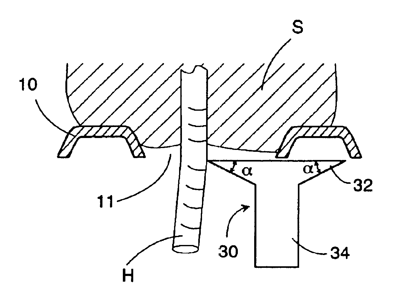
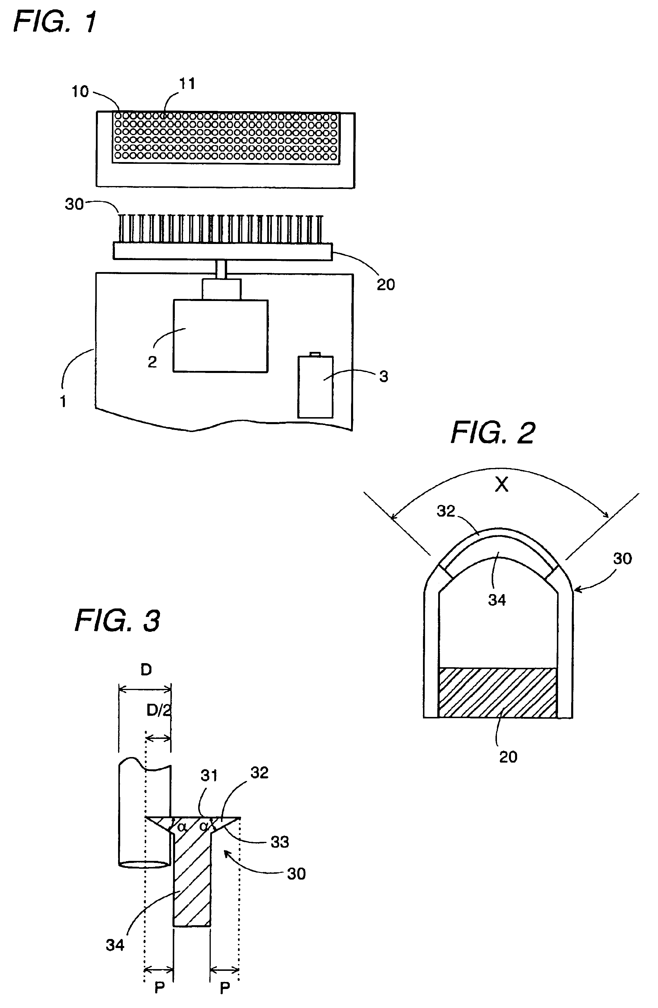
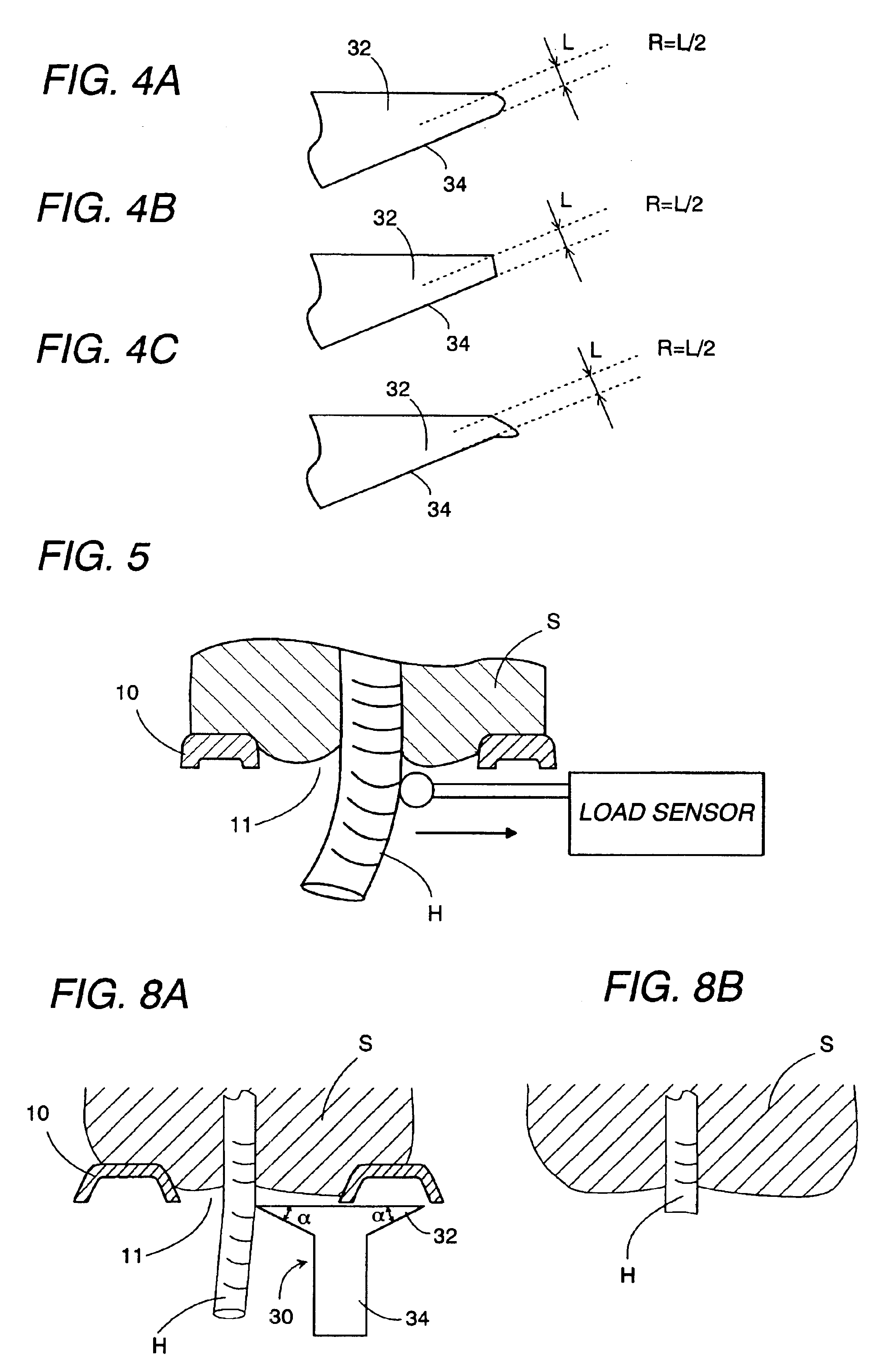
[0021]One embodiment of the present invention will be discussed with reference to the attached drawings. The inner cutter for the dry shaver in accordance with the present invention is applied to the shaver of oscillatory type, as shown in FIG. 1, and includes a plurality of blades 30 arranged in a parallel relation with each other on a base 20 of a synthetic resin. The base is connected to a driving source, for example, a motor 2 incorporated in a housing 1 to oscillate the inner cutter relative to an outer cutter 10. The outer cutter 10 has a number of hair introducing apertures 11 entrapping therein the hairs which are to be cut by the blades 30. The outer cutter 10 is secured to the upper end of the housing 1. The inner cutter projecting on the upper end of the housing 1 is driven to oscillate in a direction perpendicular to cutting edges of each blade 30 as discussed later, while being kept in contact with the inside surface of the outer cutter 10. The housing 1 accommodates a ...


PUM


Abstract

An inner cutter for a dry shaver has a plurality of blades 30 supported on a base 20 and is driven in hair-shearing engagement with an outer cutter 10 for cutting the hairs. The blades 30 are arranged in parallel with each other and are each provided on opposite sides at its top with cutting edges 32. The cutting edge 32 is defined between the top face of the blade and a rake fade 33 on the underside of the blade. The rake face 33 is inclined with respect to the top face at an angle of α (°), while the cutting edge is rounded at its tip to have a curvature radius R (μm) which satisfies a relation that R≧−0.067·α+4.7. With this result, the cutting resistance for cutting the hair can be lowered below a load necessary for bending the hair. Thus, the blade of the inner cutter can itself cut the hair without bending the hair, giving a flat cutting plane finish and enabling a close shave only with a fewer shaving strokes.

Description

TECHNICAL FIELD[0001]The present invention relates to an inner cutter for a dry shaver, and more particularly to the inner cutter having a plurality of blades arranged in parallel with each other for use in an oscillatory type electric shaver.BACKGROUND ART[0002]The electric shaver has a cutter head composed of an outer cutter having a number of hair-introducing apertures and an inner cutter provided with a plurality of blades. The inner cutter is connected to a driving source to be driven to oscillate relative to the outer cutter. As disclosed in Japanese Early Patent Publication No. 6-142347, the blade for use in the conventional inner cutter is configured to have an undercut in a side face adjacent to the top of the blade to give a cutting edge having a suitable knife angle so that, as shown in FIG. 11A, the cutting edge 32 at top of the blade 30 can shear the hairs H introduced through the aperture 11 of the outer cutter 10 against the cutter edge of outer cutter 10. In this cas...

Claims


Application Information

Patent Timeline
IPC IPC(8): B26B19/04
CPCB26B19/04B26B19/10
Inventor KAMEOKA, HIROYUKISATOU, MASAAKIKOMORI, SHUNSUKEIKUTA, TOSHIOHAMADA, TADASHI
Owner MATSUSHITA ELECTRIC WORKS LTD
Learn More