Method of positioning electrodes for central nervous system monitoring

Inactive Publication Date: 2005-09-27
INSTRUMENTARIUM CORP
View PDF13 Cites 110 Cited by
  • Summary
  • Abstract
  • Description
  • Claims
  • Application Information

AI Technical Summary

Benefits of technology

[0015]An advantage of the invention is that the method is extremely simple, practical and reliable, and therefore optimal measuring results can be obtained. Another advantage of the invention is in that the method can be materialized very simply, ie. by using a simple electrode array, whereby costs can be kept at reasonably low level.
is that the method is extremely simple, practical and reliable, and therefore optimal measuring results can be obtained. Another advantage of the invention is in that the method can be materialized very simply, ie. by using a simple electrode array, whereby costs can be kept at reasonably low level.

Problems solved by technology

The system however requires cumbersome attachment of multiple electrodes, especially when the electrodes are attached in the hair environment.
This has become a significant issue, both scientifically and commercially, in the context of measuring the depth of unconsciousness induced by anesthesia during surgery.
An anesthesia dose, which is too light can, in the worst case, cause the patient to wake up during the operation and to create a highly traumatic experience both for the patient and for the personnel administering the anesthesia.
At the opposite extreme, the administration of too deep anesthesia generates increased costs due to the excessive use of anesthesia drugs and the time needed to administer the drugs.
Over dosage of the anesthetic drugs also affects the quality and length of the post-operative period immediately after the operation and the time required for any long-term post-operative care.
In the anesthesia and the intensive care said 10-20 system is cumbersome to use.
The additional labour-consuming measuring system would take too much time and effort from the care personnel.
The consciousness level of the patient is varied in both of said environments and till today there has not been a practical method for monitoring the level of consciousness in the anesthesia and the intensive care environment.
This can create a situation where patient feels pain but cannot communicate.
Without central nervous system monitoring there is a risk of giving too little or too much anesthetics.
If too little hypnotic drugs are given to the patient he or she could awake during operation, which could cause traumatic experience especially for the patient and also for the personnel.
Another important issue about the use of EEG is defining the level of sedation in Intensive Care Units (ICU).
However, the situation in ICU is a little bit more complicated than in Operating Rooms (OR).
Without central nervous system monitoring patients are usually over sedated, which leads to longer treatment periods.
Sedation induces amnesia, which afterwards often causes physiological problems to the patients.
This is because of gap in memory.
So patient might be agitated and he or she might be eg. fighting against ventilator, which cause huge amount of artifacts to the processed signal.
If patient is not agitated he or she might be alert about surroundings, so patient can eg. move his or her eyes, which causes eye movement (EM) artifacts to the EEG.
This causes irrelevancies and non-symmetries to EEG.
Similarly these electrodes can sense pain reactions when the anesthesia is not adequate, for example because of inadequate analgesia.
So the FEMG signals give an early warning of arousal and may also indicate inadequate analgesia.
In optimally sedated patients frontalis muscle responses to noxious stimuli, but if sedation is too deep frontalis muscle is unresponsive.

Method used


Image

  • Method of positioning electrodes for central nervous system monitoring
  • Method of positioning electrodes for central nervous system monitoring
  • Method of positioning electrodes for central nervous system monitoring

Examples


third embodiment

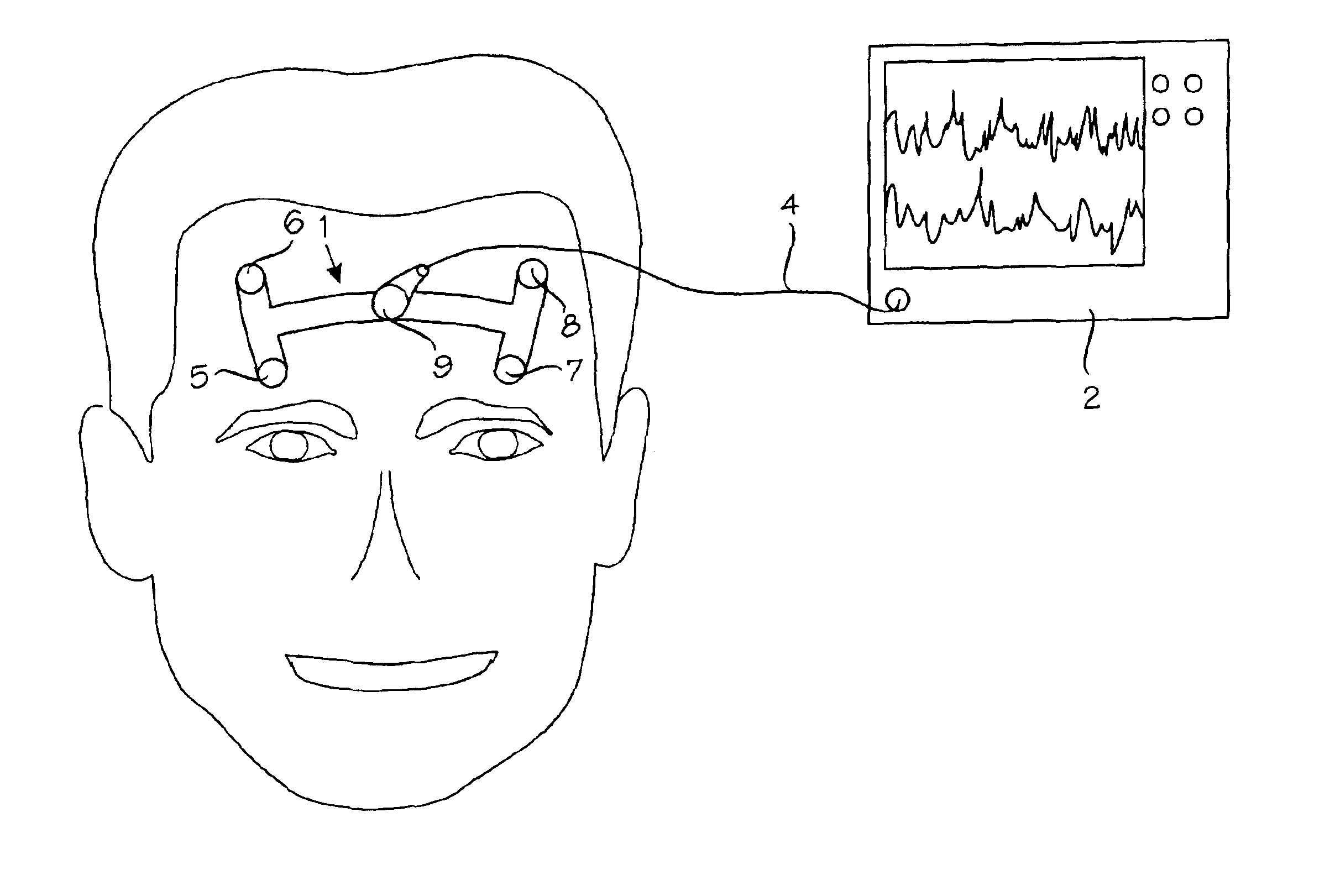
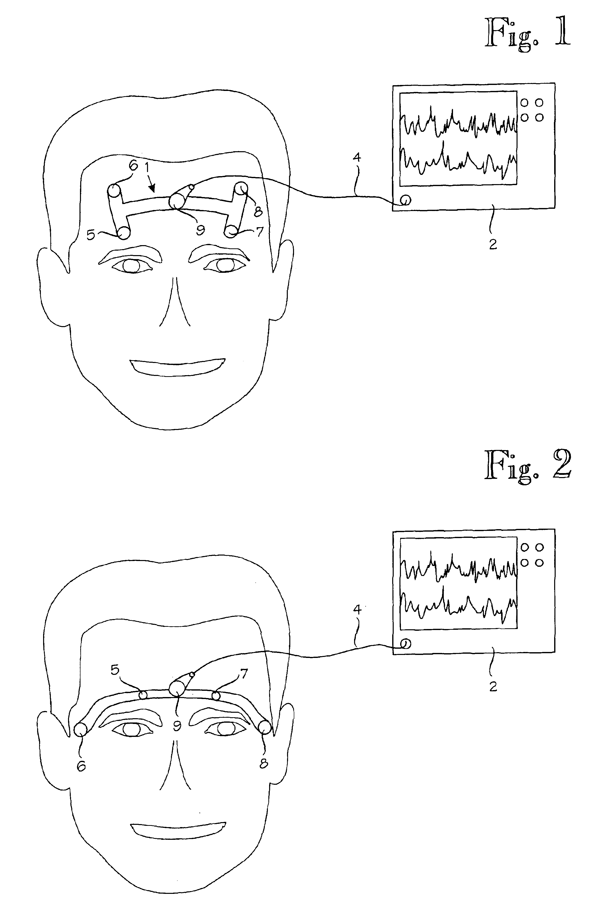
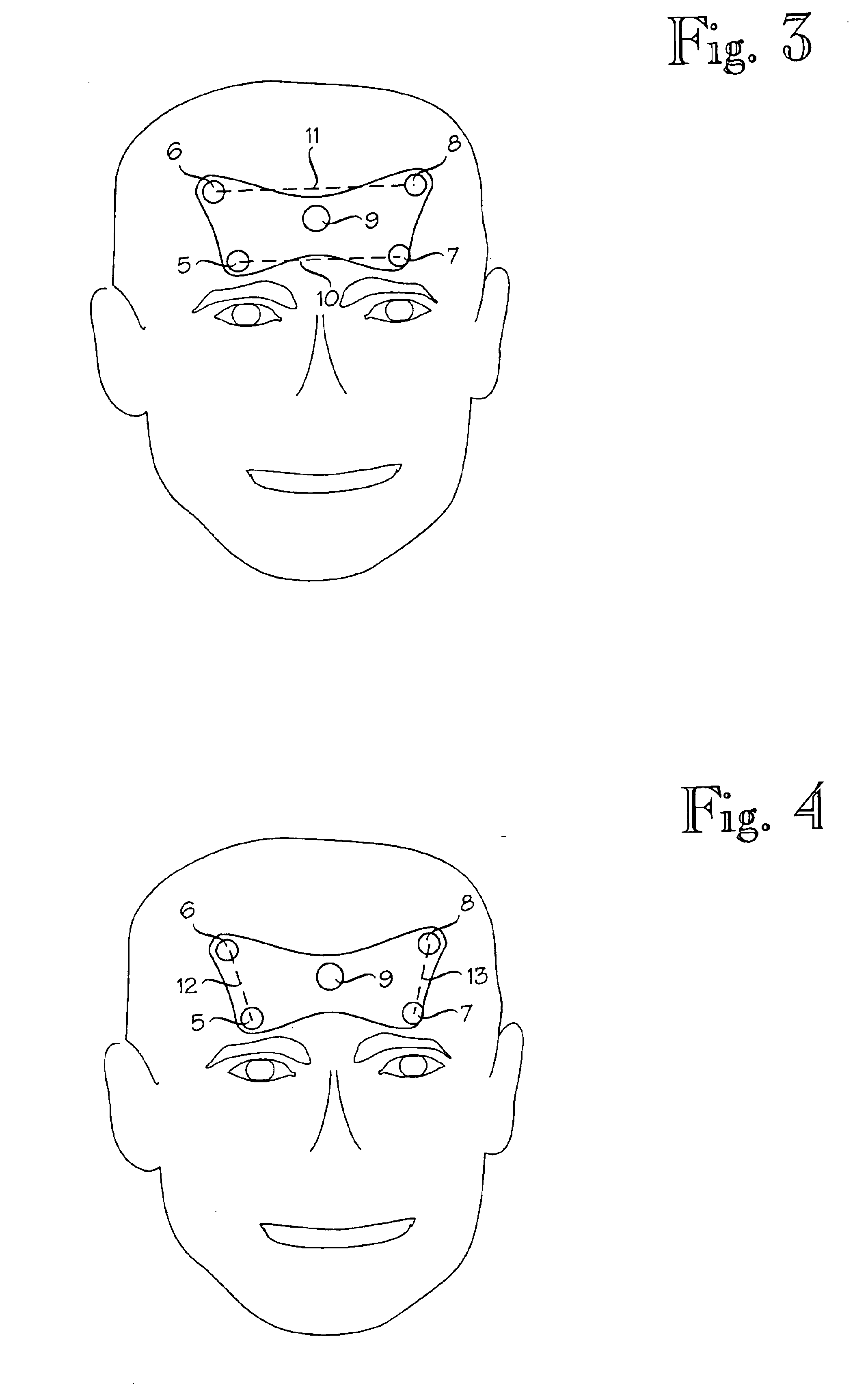
[0036]According to the basic idea of the invention it is also possible to combine the embodiments of FIG. 1 and FIG. 2. This combination, ie. the invention is shown in FIG. 6. In FIG. 6 corresponding details in different embodiments have been marked with same reference numerals as in FIGS. 1 and 2. In this embodiment the first electrode, the third electrode and the fifth electrode (ground electrode) are marked with the same reference numerals as in FIGS. 1 and 2. Said electrodes 5, 7 and 9 are placed in the same way as described in connection with FIG. 1.

[0037]The embodiment shown in FIG. 6 uses an array of seven electrodes. Location of the electrodes are those described in connection with. FIGS. 1 and 2. In the embodiment shown the second electrode is marked with a reference number 6a and the sixth electrode is marked with a reference number 6b. The fourth electrode is marked with a reference number 8a and the seventh electrode is marked with a reference number 8b. The second elect...

second embodiment

[0038]The seven-electrode system described above and shown in FIG. 6 offers different montages to measure biopotential signals from the patient. It is easy to understand that this embodiment offers the montages already discussed in connection with the embodiments of FIGS. 1 and 2. The main advantage of the embodiment of FIG. 6 is that it offers all of the benefits discussed with the embodiments of FIGS. 1 and 2 simultaneously, switching between montages is not necessary needed. FIG. 7 shows one possible montage in phantom lines. Bipolar montage between electrodes 6a and 8a is used to measure EEG. Bipolar montages between electrodes 5 and 6b and between electrodes 7 and 8b are used to measure EMG and eye movements and to identify nonsymmetries between hemispheres. FIG. 8 shows another possible montage in phantom lines. Bipolar montage between electrodes 5 and 7 is used to measure EMG. Bipolar montages between electrodes 6a and 6b and between electrodes 8a and 8b are used to measure E...


PUM


Abstract

Method of positioning electrodes in an electrode array, comprising at least five or at least seven electrodes for central nervous system (CNS) monitoring from the forehead of a patient's head. The electrodes of the array are optimally located for discriminating EEG, FEMG and EM components from the recorded biopotential signals.

Description

BACKGROUND OF THE INVENTION[0001]The present invention relates to a method for central nervous system (CNS) monitoring, and more specifically to a method of positioning electrodes in an electrode array comprising at least five or at least seven electrodes for monitoring central nervous system with the help of electroencephalography (EEG), frontal electromyography (FEMG) and eye movement (EM) signals from the forehead of a patient's head. The invention also relates to a method of sensing pain reactions of a patient.[0002]Electroencephalography (EEG) is a well-established method for assessing the brain function by picking up the weak signals generated in the brain with electrodes on the skull surface. To obtain the signals, multiple electrodes are placed on the scalp of a patient in accordance with a recognized protocol. EEG has been in wide use for decades in basic research of the neural system of brain as well as clinically in diagnosis of various neurophysiological disorders.[0003]...

Claims


Application Information

Patent Timeline
IPC IPC(8): A61B5/0492A61B5/0488A61B5/0476A61B5/0478A61B5/0408A61B5/0496A61B5/11A61B5/296
CPCA61B5/0478A61B5/0492A61B5/4821A61B5/04085A61B5/0496A61B5/1106A61B5/282A61B5/291A61B5/398A61B5/296
Inventor SARKELA, MIKAVIERTIO-OJA, HANNA
Owner INSTRUMENTARIUM CORP
Why Eureka
Try Eureka