
Planar motor

a technology of a plane motor and a control panel, applied in the direction of motor/generator/converter stopper, dynamo-electric converter control, instruments, etc., can solve the problems of inability to eliminate vibration during operation, adversely affect responsiveness and accuracy, and difficulty in reducing the thickness of the blade, etc., to achieve high accuracy, control vibration, and thin design

Inactive Publication Date: 2005-09-27
CHIBA PRECISION
View PDF4 Cites 18 Cited by
  • Summary
  • Abstract
  • Description
  • Claims
  • Application Information

AI Technical Summary

Benefits of technology

"The present invention provides a planar motor that allows for a thinner design, controlled vibration, and highly accurate positioning without using an expensive linear guide. The motor includes a movable stage with permanent magnets and a fixed stage with coils, along with a cross-shaped common electrode and fixed electrodes. The motor uses capacitance displacement sensors to measure the movement of the movable stage in the planar direction. The motor can be controlled in the X, Y, and θ directions by calculating the displacements of the capacitors and using a comparative arithmetic circuit. The technical effects of the invention include a thinner design, controlled vibration, and highly accurate positioning without the need for an expensive linear guide."

Problems solved by technology

The first planar motor described above has the stack construction, making it difficult to reduce its thickness.
Furthermore, the planar motor requires more mechanical components, which adversely affects responsiveness and accuracy due to lost motion from backlashes or stage weight.
Furthermore, vibration during operation cannot be eliminated even if an ingenious control means is adopted.
The third planar motor requires an expensive peripheral device for positional detection and involves difficult alignment at installation.

Method used


Image

  • Planar motor
  • Planar motor
  • Planar motor

Examples


Embodiment Construction

[0022]An embodiment of the present invention will now be explained in detail with reference to the accompanying drawings.

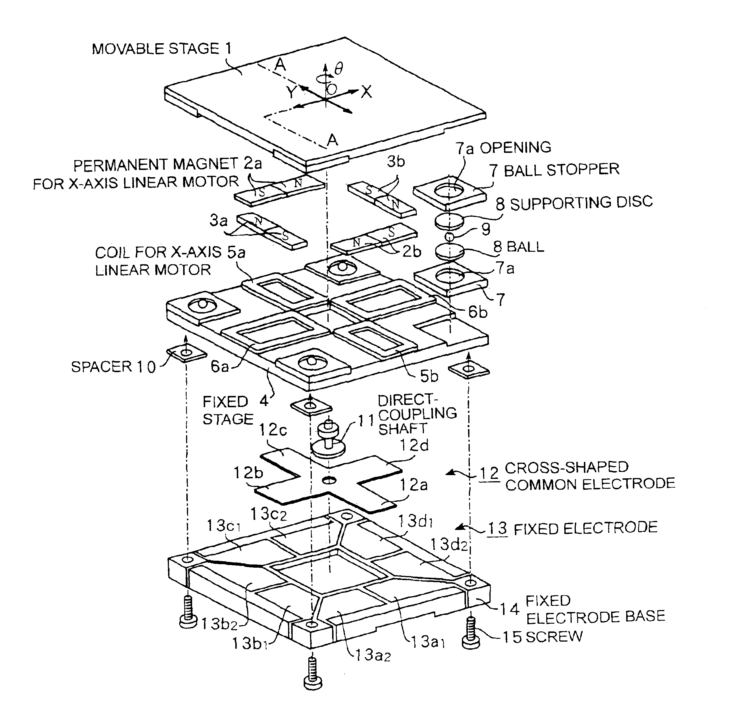
[0023]FIG. 1 is an exploded perspective view showing the embodiment of a planar motor in accordance with the present invention.

[0024]This embodiment is an example of a movable magnet type planar motor formed of permanent magnets and coils. A planar motor is basically constructed of an X-axis linear motor structure and a Y-axis linear motor structure disposed to be geometrically orthogonal with respect to the X-axis linear motor structure, these two linear motors being installed on the same plane.

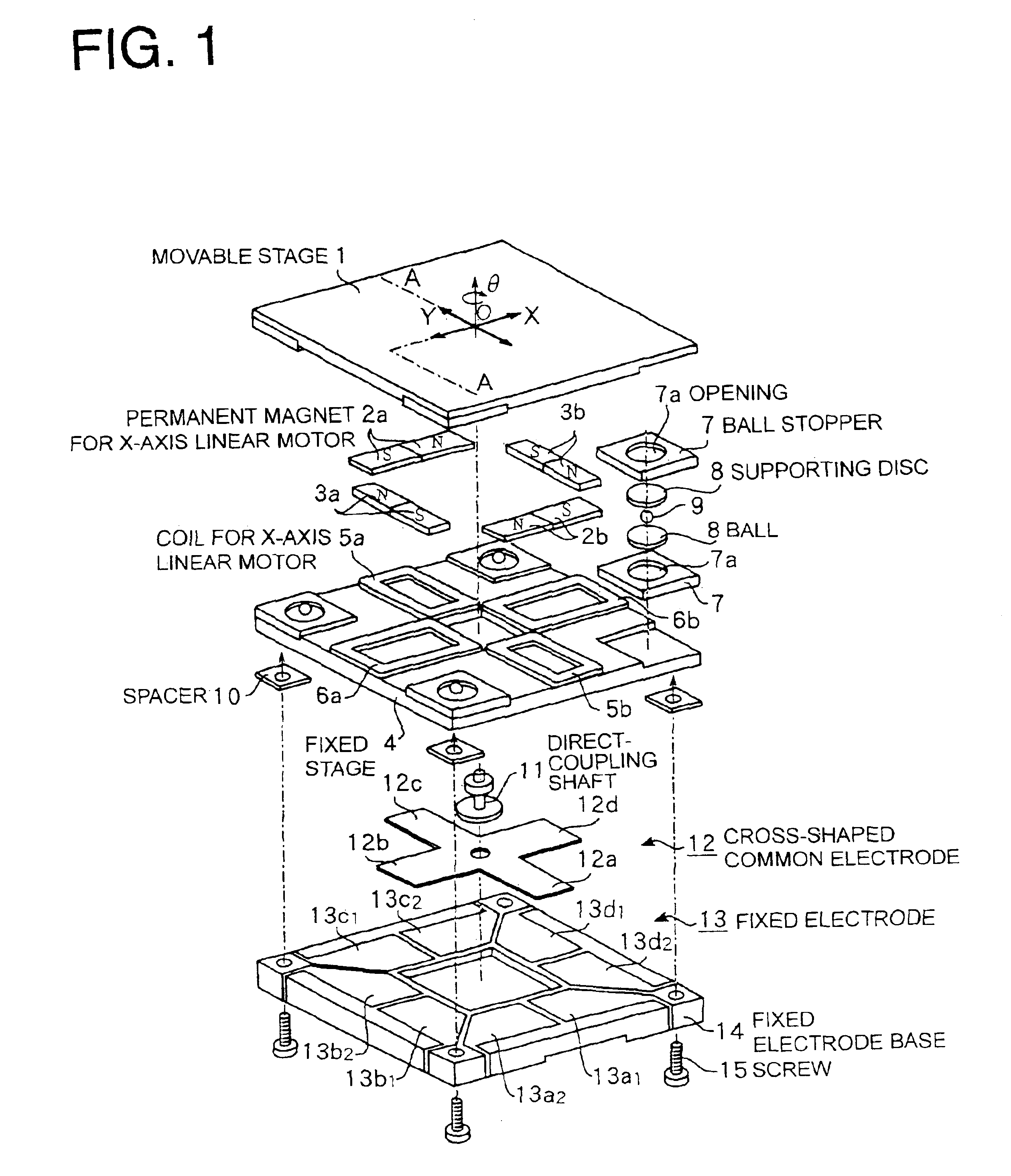
[0025]The X-axis linear motor structure has a pair of permanent magnets 2a and 2b mounted on the bottom surface of a movable stage 1 made of a ferromagnetic member, and planar coils 5a and 5b made of a ferromagnetic member and disposed on the top surface of a fixed stage 4. The planar coils 5a and 5b are interlinked with magnetic fluxes of the permanent magnets 2a and 2b. ...


PUM


Abstract

A planar motor permits a thinner design, controlled vibration, and highly accurate positioning by disposing X-axis and Y-axis coreless type linear motors on the same plane without using an expensive linear guide and by incorporating high-accuracy capacitance displacement sensors in X and Y directions. Two pairs of permanent magnets are disposed such that they are respectively orthogonalized with respect to two axes that are orthogonalized with each other on a movable stage and that they generate magnetic fluxes in a direction perpendicular to a surface of the movable stage. Furthermore, the permanent magnets of one pair are disposed symmetrically to each other about one of the two axes, while those of the other pair are disposed symmetrically to each other about the other axis. Two pairs of coils are provided such that they oppose and match the two pairs of permanent magnets. A cross-shaped common electrode is installed to the movable stage and disposed such that it opposes a fixed electrode composed of two electrodes disposed on a fixed electrode base. Displacements of the movable stage can be determined from changes in capacitance of capacitors formed by the cross-shaped common electrode and the fixed electrodes.

Description

BACKGROUND OF THE INVENTION[0001]1. Field of the Invention[0002]The present invention relates to a planar motor used for performing fine positional control of a stage of a microscope or the like.[0003]2. Description of the Related Art[0004]Hitherto, as a device adapted to position an object two-dimensionally in X-axis and Y-axis directions, an X-Y stage is widely known. The X-Y stage is constructed of a stage that includes ball screws and servo motors installed in a linear guide and extends in one direction, and another stage stacked in the direction orthogonal with respect to the above stage.[0005]Another well-known planar motor has a X-axis drive linear motor and a Y-axis drive linear motor of variable reluctance type pulse motors that are disposed on the same plane, as disclosed in Japanese Unexamined Patent Application Publication No. H10-75562. Still another well-known planar motor has a biaxial linear motor and a plurality of laser interferometers used as position detectors fo...

Claims


Application Information

Patent Timeline
Patent Type & Authority Patents(United States)
IPC IPC(8): H02P25/02H02P25/06H02K11/00H02K41/02G01B7/00H02K41/03H02K41/035
CPCH02K41/03H02P25/06H02K2201/18
Inventor OISUGI, YUTAKASATO, HIDEAKI
Owner CHIBA PRECISION
Learn More