
Device for plugging an opening such as in a wall of a hollow or tubular organ including biodegradable elements

a biodegradable element and device technology, applied in the field of implants, can solve problems such as unfixed maneuverability

Inactive Publication Date: 2005-09-27
CARAG AG
View PDF29 Cites 79 Cited by
  • Summary
  • Abstract
  • Description
  • Claims
  • Application Information

AI Technical Summary

Benefits of technology

[0007]A carrier rod is releasably attached to the first holder and upon which the second holder is slidably received. The plurality of members with the occluding body form an elongated article extending along a longitudinal axis adapted for insertion through an intravenous delivery mechanism in an insertion condition. A driving implement is located on the carrier rod, the driving implement contacting the second holder and movable toward the first holder along the carrier rod. The members are attached to the first and second holders at respective ends and at a mid-span to the occluding body in a manner to cause the members to execute a twisting motion relative to the longitudinal axis to yield a plurality of generally radially extending loops combining to form a first fixation structure adjacent the distal face of the occluding body, and a second fixation structure of generally radially extending loops adjacent the proximal face of the occluding body. The first and second fixation structures may twist into a plurality of helical loops that are oriented in opposite directions from each other. A locking element may fix the first and second attachment members in a final occluding condition upon being driven together by the driving implement.

Problems solved by technology

The cause of the nonsecure closing capacity is the relative unfixed maneuverability for the closing part when applied around the passage, and that the application takes part long before it has arrived in its final position around the passage in the heart.

Method used


Image

  • Device for plugging an opening such as in a wall of a hollow or tubular organ including biodegradable elements
  • Device for plugging an opening such as in a wall of a hollow or tubular organ including biodegradable elements
  • Device for plugging an opening such as in a wall of a hollow or tubular organ including biodegradable elements

Examples


Embodiment Construction

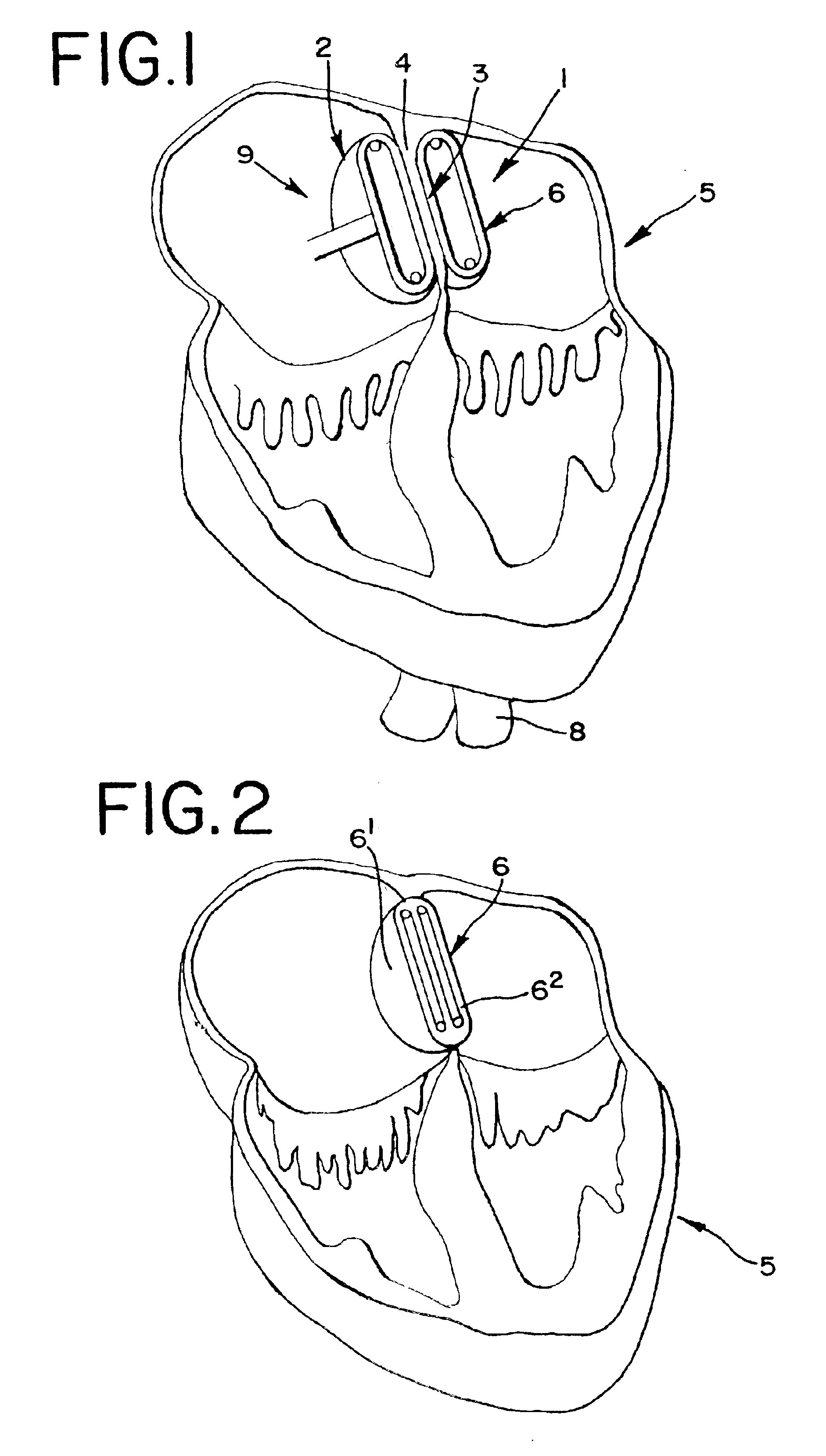
[0030]The invention has found particular application as a cardiological implant by means of which it is possible, for example, to close an aperture through the auricle diaphragm or the ventricle diaphragm of a heart.

[0031]The implant according to the present invention is arranged to be deployed or built up (i.e., assembled) at a desired location in the body (e.g., the heart), in contrast to known implants (e.g., so-called umbrellas and sails) that are instead extended as soon as the compressed umbrella leaves its insertion sheath.

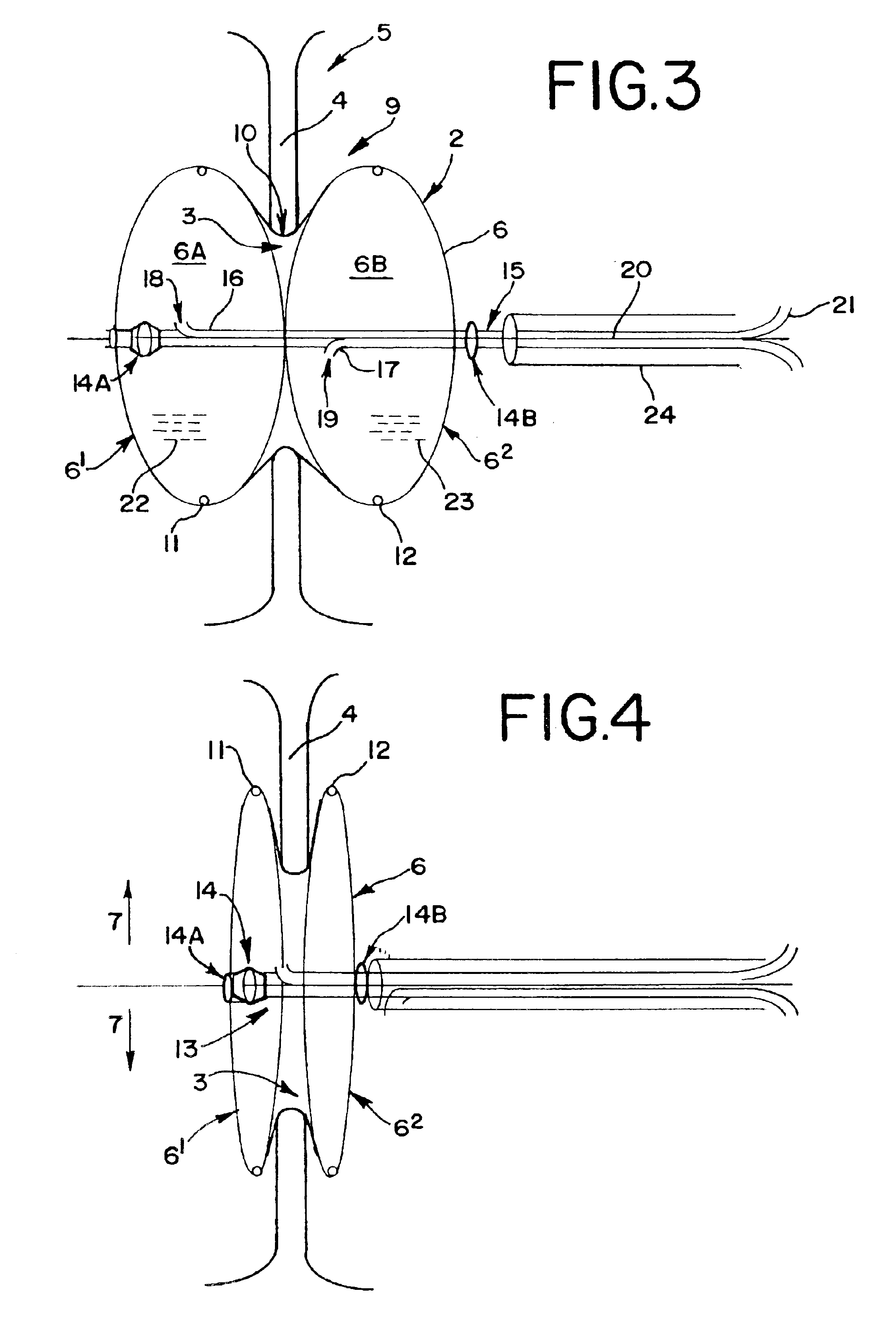
[0032]According to the invention, a device 1 is employed as an implant 2 for closing an internal passage 3, for example, an aperture in the auricle diaphragm 4 or the ventricle diaphragm of a heart 5, or in a desired body channel which one wishes to close. A closing body 6 is deployed or built up at the location. More particularly, an embodiment of the invention that is shown on the drawings in FIGS. 1-5, is formed in a radial direction 7 of expanding and s...


PUM

PropertyMeasurementUnit
degradation timeaaaaaaaaaa
tensile strengthsaaaaaaaaaa
tensile strengthaaaaaaaaaa

Abstract

An implant for occluding a passage in a circulatory system is provided. The implant in one form includes a plurality of thin wire-like members each having a proximal and a distal end and a first holder to which the distal ends of the members are attached. The proximal ends of the members are attached to a second holder. The implant includes an expansible occluding body attached to the members at a point intermediate the first and second holders. A carrier rod is releasably attached to the first holder and upon which the second holder is slidably received. A driving implement is located on the carrier rod, the driving implement contacting the second holder and movable toward the first holder along the carrier rod. The members are attached to the first and second holders in a manner to cause the members to execute a twisting motion relative to the longitudinal axis to yield a plurality of generally radially extending loops combining to form a first fixation structure adjacent the distal face of the occluding body, and a second fixation structure of generally radially extending loops adjacent the proximal face of the occluding body. In another form, the implant includes a balloon structure which is expanded from within by a spring-like mechanism in situ, or by the foregoing radially extending loop mechanism.

Description

APPLICATION HISTORY[0001]This application is a continuation-in-part of U.S. patent Ser. No. 09 / 707,691 filed Nov. 7, 2000, now U.S. Pat. No. 6,488,706, issued Dec. 3, 2002, which is a continuation-in-part of U.S. Ser. No. 09 / 180,379 filed Nov. 6, 1998, now abandoned, which claims priority to PCT / SE97 / 00747 filed May 6, 1997, and to Sweden 9601752-0 filed May 8, 1996.FIELD OF THE INVENTION[0002]The present invention generally relates to an implant device for closing a body passage (e.g., an aperture through the auricle diaphragm or the ventricle diaphragm of a heart) or in a body channel, and more particularly comprising an occluding or closing body which is expanded and fixed into place at the passage area to be occluded / closed. In one embodiment, the implant device may be entirely or partly biodegradable.BACKGROUND OF THE INVENTION[0003]By way of example EP 0 362 113 B1 shows a device for closing a passage in the heart of patients, wherein the closing part runs the risk of tipping ...

Claims


Application Information

Patent Timeline
Patent Type & Authority Patents(United States)
IPC IPC(8): A61B17/12A61B17/00A61F2/24A61L31/06A61L31/14
CPCA61B17/0057A61B17/12022A61B17/12109A61B17/12172A61L31/06A61L31/148C08L67/04A61B2017/00557A61B2017/00575A61B2017/00592A61B2017/00606A61B2017/00619A61B2017/00623A61B2017/00867
Inventor SOLYMAR, LASZLOTHOMMEN, DANIEL THOMASBERNHARD, JEROME
Owner CARAG AG
Learn More