
Method and apparatus for providing force feedback using multiple grounded actuators

a technology of grounded actuators and force feedback, applied in the field of interface devices, can solve the problems of not providing force feedback to users, corrupting the system bandwidth, and not allowing users to experience an entire sensory dimension in virtual reality simulations, and achieve high-realism force feedback and low inertial contribution to the system

Inactive Publication Date: 2005-09-20
IMMERSION CORPORATION
View PDF171 Cites 82 Cited by
  • Summary
  • Abstract
  • Description
  • Claims
  • Application Information

AI Technical Summary

Benefits of technology

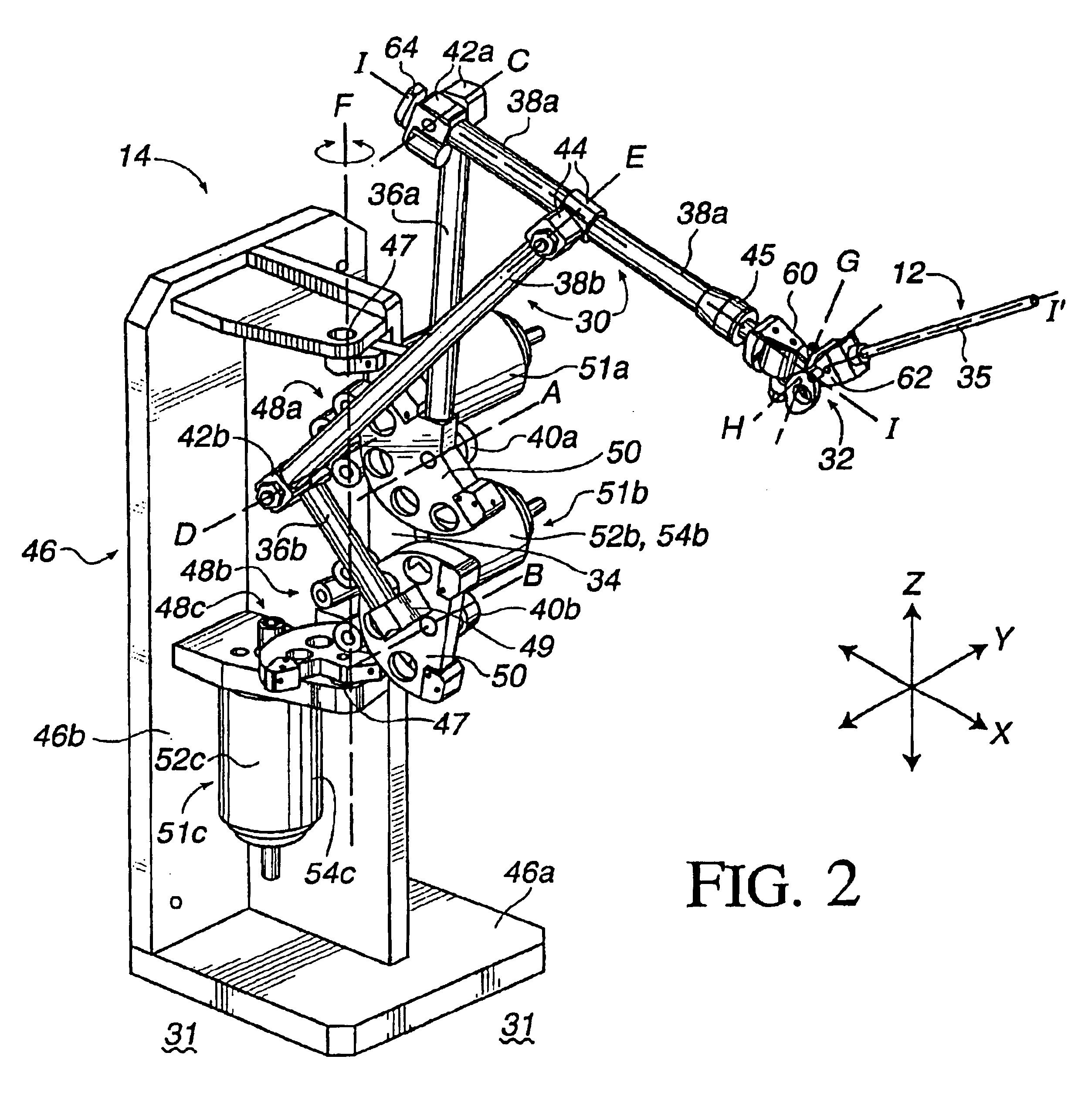
[0011]The present invention provides a human / computer interface apparatus and method which can provide from one to six degrees of freedom to a user-manipulable object and highly realistic force feedback to the user of the apparatus. The structure of the apparatus and a capstan drive permits actuators to be grounded and thus positioned such that their inertial contribution to the system is very low.
[0012]An interface apparatus and method of the present invention for interfacing the motion of a user-manipulable object with a computer system includes a user manipulable object physically contacted by a user, such as a stylus, medical / surgical instrument, joystick, or other graspable object. A 3-D spatial mechanism is coupled to the user object and provides at least three degrees of freedom to the user object, where the spatial mechanism includes multiple members including a ground member coupled to ground. Three actuators are rigidly coupled to the ground member and together apply a three-dimensional force to the user manipulable object in response to actuator signals from the computer system. Each actuator does not carry the weight of any of the other actuators, thus providing a highly accurate and realistic 3-D interface for the user. A sensor for detecting a position of said user manipulable object along said degree of freedom and outputting sensor signals to said computer system. A sensor detects a position of the user object along the degree of freedom and outputs sensor signals to the electrical system.
[0013]The spatial mechanism preferably includes a planar five-member closed loop linkage riding on a rotatable carriage. The five-member linkage provides two degrees of freedom to the user manipulable object and includes two base members, two central members, and a ground member. The rotatable carriage is coupled to the ground member and provides a third degree of freedom to the user manipulable object. Force is transmitted from each said actuators to the spatial mechanism using capstan drive mechanisms. Two of the capstan drive mechanisms each include a drum coupled to the carriage such that a member of the spatial mechanism is coupled to the drum, and a pulley coupled to a grounded actuator. A drum is coupled to a corresponding pulley by a cable or other flexible member so that the actuator is operative to rotate the pulley and transmit force to the spatial mechanism in the first two degrees of freedom with no substantial backlash. Since the drums are coupled to the carriage, the pulley is coupled to the grounded actuator, and the cable between them is flexible, the drums may be rotated with the carriage while the pulleys remain fixed in position and the cable twists, thus providing a third degree of freedom for the user object. A third capstan drive mechanism is also preferably coupled between the the carriage and the grounded third actuator to provide forces in the third degree of freedom. Thus, all three actuators are grounded and decoupled in force from each other, thereby avoiding the inertia created by the weight of the actuators being carried by other actuators or carried by the user.
[0014]An interface apparatus of the present invention also may include a floating gimbal mechanism coupling one of the members of a linkage or other mechanism to the user manipulatable object. The floating gimbal mechanism includes a plurality of rotatably coupled gimbal members that provide two rotary degrees of freedom to the user manipulable object. A sensor is provided for each of the gimbal members for measuring a position of the members relative to each other in one of the rotary degrees of freedom. Preferably, a capstan mechanism is coupled between each of the sensors and one of the gimbal members, where each capstan mechanism includes a capstan drum rotatable about an axis of one of the rotary degrees of freedom and a pulley coupled to the sensor and coupled to the drum by a flexible member, such as a metal cable. The capstan mechanisms provide mechanical reduction and thus enhance the resolution of the sensors. In other embodiments, the user manipulable object is rotatable about a longitudinal axis of the object to provide an additional degree of freedom for the object.
[0015]The interface apparatus of the present invention includes three grounded, decoupled actuators to provide forces in three degrees of freedom of a user manipulable object. This improvement allows the user to manipulate the object free from the inertia caused by the weight of the actuators, and allows the other actuators to transmit forces to the user object without having to compensate for the inertia of other actuators, thereby providing more accurate and realistic forces. These unique twist capstan drive mechanisms allow the three actuators to be grounded while also providing mechanical advantage for the high bandwidth and low backlash forces from the actuators. The floating gimbal mechanism of the present invention provides capstan mechanisms in a unique configuration that allows the sensing resolution of the floating gimbal sensors to be enhanced while minimizing the weight of the floating gimbal mechanism. These improvements allow a computer system to have more complete and accurate control over a low-cost interface providing realistic force feedback.

Problems solved by technology

The Immersion Probe, however, does not provide force feedback to a user and thus does not allow a user to experience an entire sensory dimension in virtual reality simulations.
Since actuators which supply force feedback tend to be heavier and larger than sensors, they would provide inertial constraints if added to a device such as the Immersion Probe.
The end result is high inertia which corrupts the bandwidth of the system, providing the user with an inaccurate interface.
These interfaces also introduce tactile “noise” to the user through friction and compliance in signal transmission and limit the degree of sensitivity conveyed to the user through the actuators of the device.
However, these systems are limited in bandwidth by their mechanisms, which tend to be inaccurate and ill-suited for effectively transmitting forces to the user.
However, if it is desired to provide forces in a third degree of freedom, then the user is typically required to carry the weight of the third actuator supplying force in that third degree of freedom, which degrades the realism of the forces felt using the force feedback interface device.
However, in many of these interface systems, the forces from one motor influence the tension on other motors and cables in the system, thus causing additional degradation in the force transmission.
In addition, the calculation of forces to provide a desired force sensation to the user can be complicated in such a coupled actuator system, thus decreasing the response time of the system.

Method used


Image

  • Method and apparatus for providing force feedback using multiple grounded actuators
  • Method and apparatus for providing force feedback using multiple grounded actuators
  • Method and apparatus for providing force feedback using multiple grounded actuators

Examples


Embodiment Construction

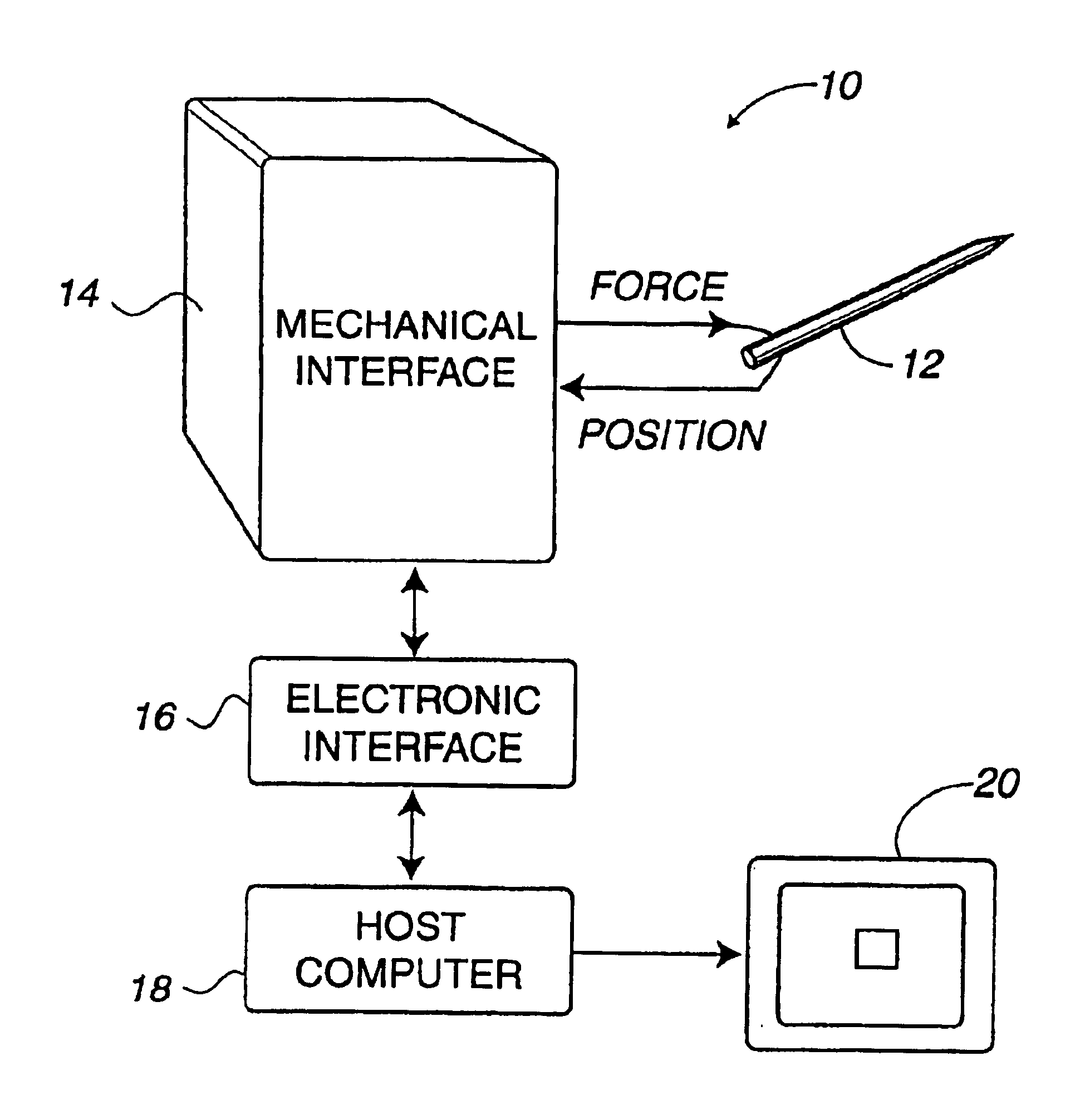
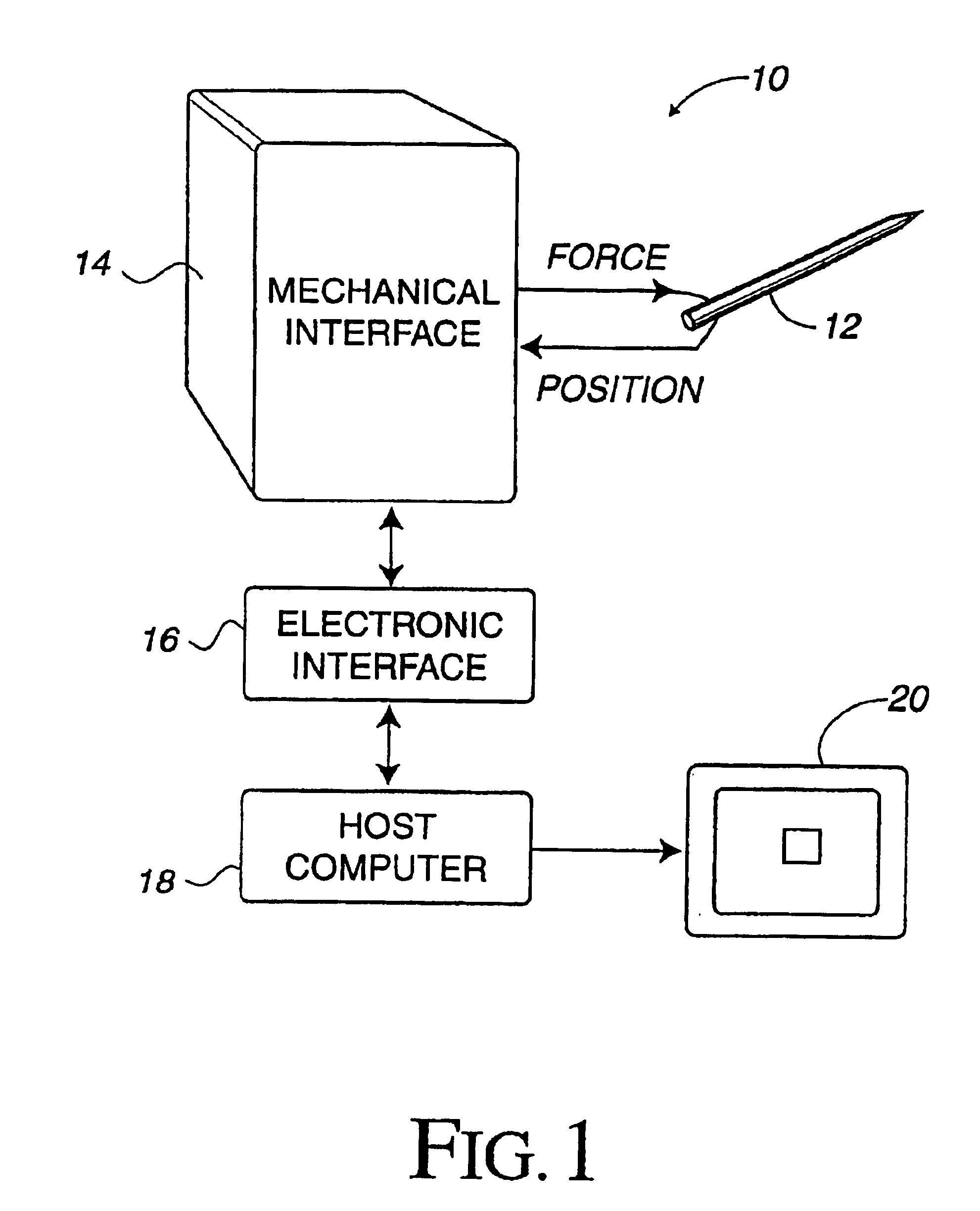
[0029]FIG. 1 illustrates a force feedback virtual reality system 10 used to provide a user-manipulable object in a virtual environment, simulation, or video game. Virtual reality system 10 includes a user manipulable object 12, a mechanical interface 14, an electronic interface 16, and a host computer 18. The illustrated virtual reality system 10 includes a stylus 12 as a user manipulable object.

[0030]User manipulable 12 used in conjunction with the present invention is manipulated by a user and, for example, virtual reality images are displayed on a display screen 20 of the computer system 18 in response to such manipulations. For example, a user can move a stylus 12 to correspondingly move a computer generated object, such as a cursor or other image, in a virtual environment. The available degrees of freedom in which user manipulable object 12 can be moved are determined from the mechanical interface 14, described below.

[0031]It will be appreciated that a great number of other typ...


PUM


Abstract

An apparatus and method for interfacing the motion of a user-manipulable object with a computer system includes a user object physically contacted or grasped by a user. A 3-D spatial mechanism is coupled to the user object, such as a stylus or a medical instrument, and provides three degrees of freedom to the user object. Three grounded actuators provide forces in the three degrees of freedom. Two of the degrees of freedom are a planar workspace provided by a closed-loop linkage of members, and the third degree of freedom is rotation of the planar workspace provided by a rotatable carriage. Capstan drive mechanisms transmit forces between actuators and the user object and include drums coupled to the carriage, pulleys coupled to-grounded actuators, and flexible cables transmitting force between the pulleys and the drums. The flexibility of the cable allows the drums to rotate with the carriage while the pulleys and actuators remain fixed to ground. The interface also may include a floating gimbal mechanism coupling the linkage to the user object. The floating gimbal mechanism includes rotatably coupled gimbal members that provide three degrees of freedom to the user object and capstan mechanisms coupled between sensors and the gimbal members for providing enhanced sensor resolution.

Description

[0001]This application is a continuation of Ser. No. 08 / 736,161 filing date Oct. 25, 1996 now U.S. Pat. No. 5,828,197.BACKGROUND OF THE INVENTION[0002]The present invention relates generally to interface devices between humans and computers, and more particularly to computer interface devices that provide force feedback to the user.[0003]Virtual reality computer systems provide users with the illusion that they are part of a “virtual” environment. A virtual reality system will typically include a computer processor, such as a personal computer or workstation, specialized virtual reality software, and virtual reality I / O devices such as head mounted displays, sensor gloves, three dimensional (“3D”) pointers, etc.[0004]Virtual reality computer systems can be used for training. In many fields, such as aviation and vehicle and systems operation, virtual reality systems have been used successfully to allow a user to learn from and experience a realistic “virtual” environment. The appeal ...

Claims


Application Information

Patent Timeline
IPC IPC(8): A61B19/00B25J9/16G06F3/033G09B23/00G09B23/28
CPCA61B19/22B25J9/1689G06F3/0346G09B23/28A61B2019/2242A61B2019/2276A61B2019/2292G05B2219/35419G05B2219/40144A61B2034/742A61B34/70A61B34/71A61B34/76
Inventor MARTIN, KENNETH M.LEVIN, MIKE D.ROSENBERG, LOUIS B.
Owner IMMERSION CORPORATION
Learn More