
Electric motor drive for a reel mower

a technology of electric motor and reel mower, which is applied in the direction of dynamo-electric components, dynamo-electric machines, agriculture tools and machines, etc., can solve the problems of loss and heat generation caused by eddy current in the magnets, and the failure of the motor, so as to achieve sufficient heat dissipation and power output, avoid damage, and be easily removed for maintenance and repair.

Inactive Publication Date: 2005-09-20
DEERE & CO
View PDF27 Cites 30 Cited by
  • Summary
  • Abstract
  • Description
  • Claims
  • Application Information

AI Technical Summary

Benefits of technology

[0016]According to another aspect of the invention, the casing is mounted to the frame by at least one threaded member engaged into a slot, wherein loosening of the threaded member permits withdrawal of the threaded member from the slot in a direction substantially perpendicular to an axial direction of the threaded member.
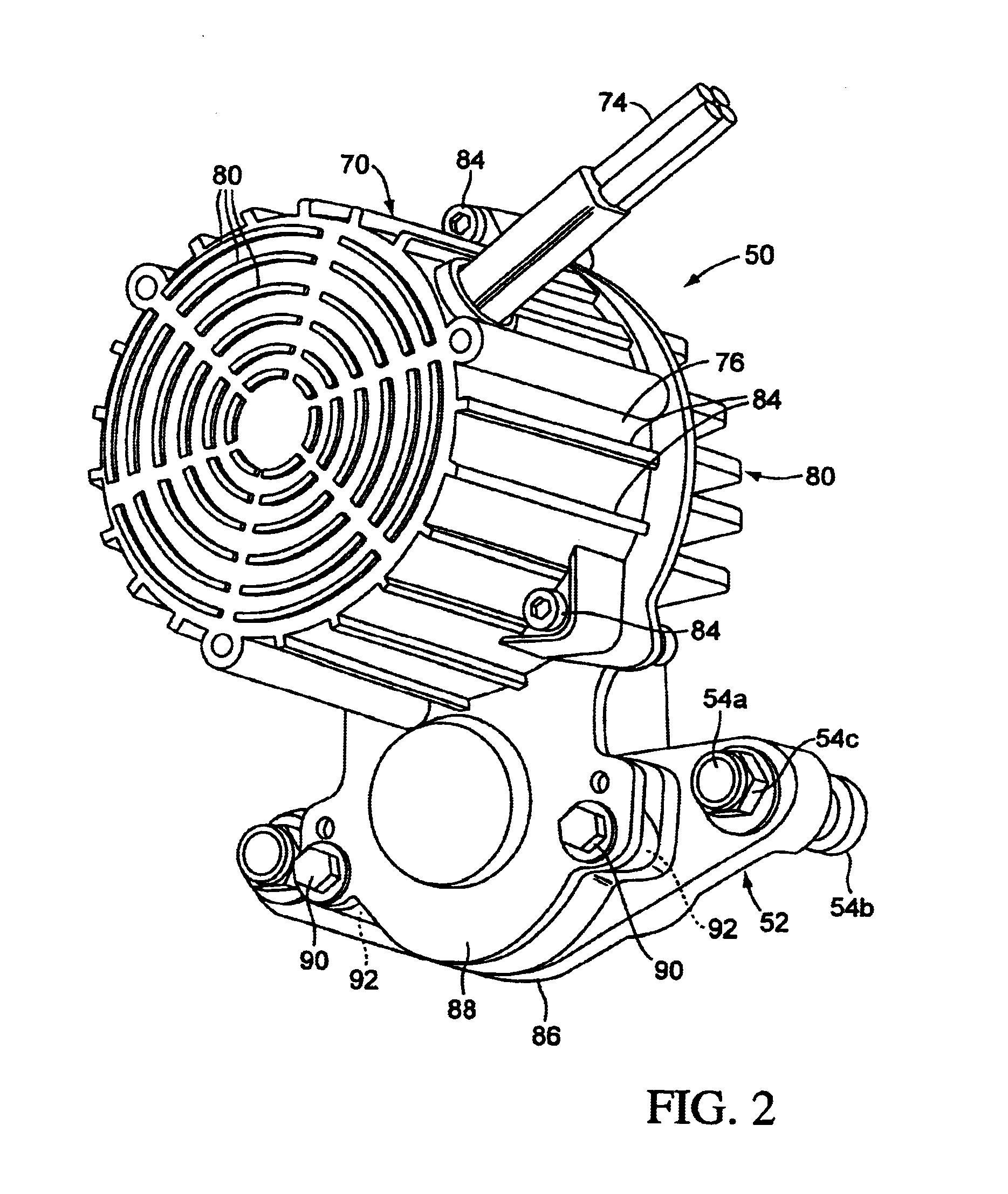
[0018]The invention provides an electric motor drive that maintains sufficient heat dissipation and power output to drive a typical reel mower. The invention provides an end-mounted electric motor assembly that avoids damage by being elevated from the ground. The present invention provides a motor assembly that is quickly and easily removable for maintenance and repair.

Problems solved by technology

The problem of loss and heat generation due to eddy currents in the magnets is significant.
Heat generation in a motor leads to demagnetization of the magnet, and can result in a failure of the motor.

Method used


Image

  • Electric motor drive for a reel mower
  • Electric motor drive for a reel mower
  • Electric motor drive for a reel mower

Examples


Embodiment Construction

[0027]While this invention is susceptible of embodiment in many different forms, there are shown in the drawings, and will be described herein in detail, specific embodiments thereof with the understanding that the present disclosure is to be considered as an exemplification of the principles of the invention and is not intended to limit the invention to the specific embodiments illustrated.

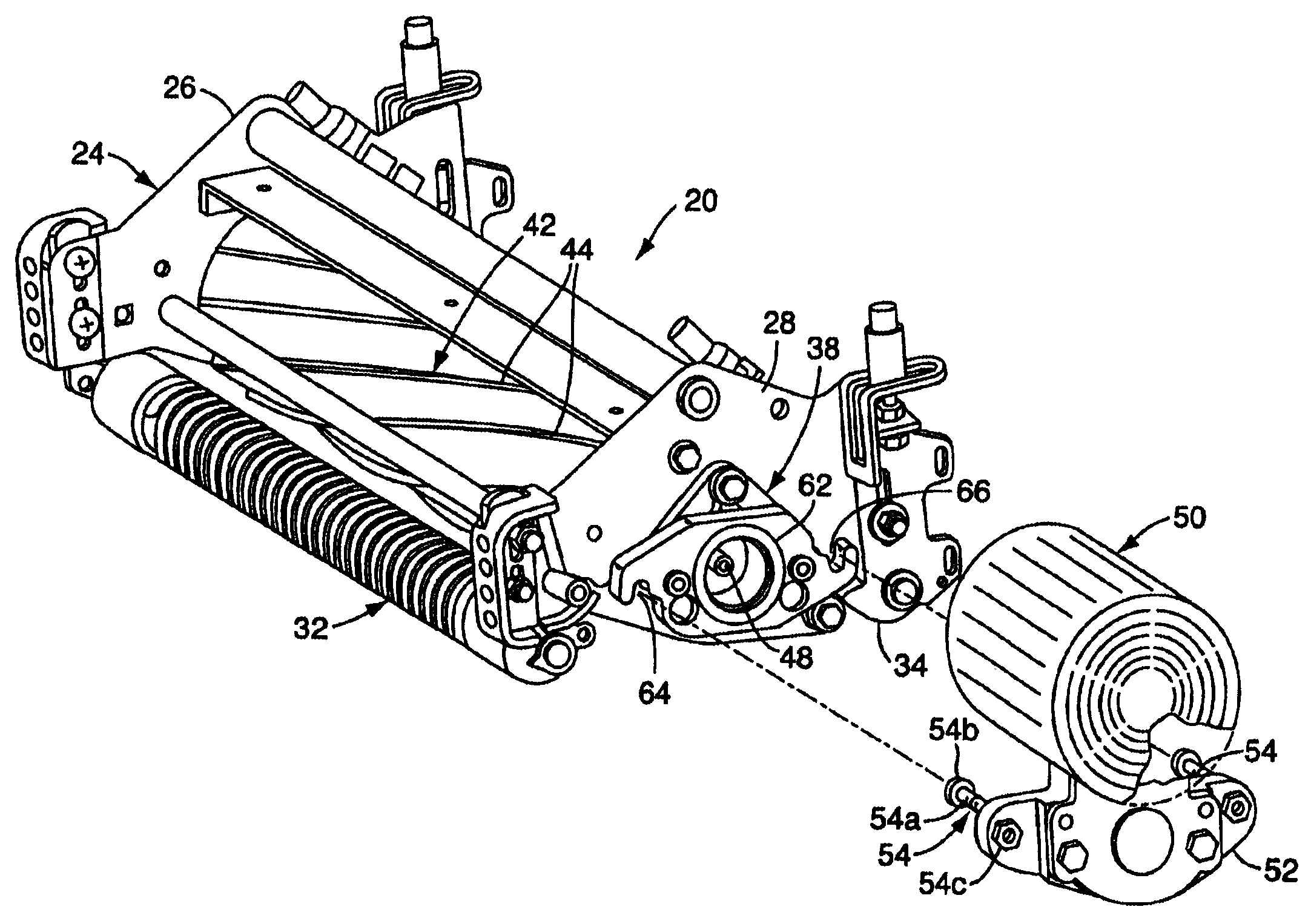
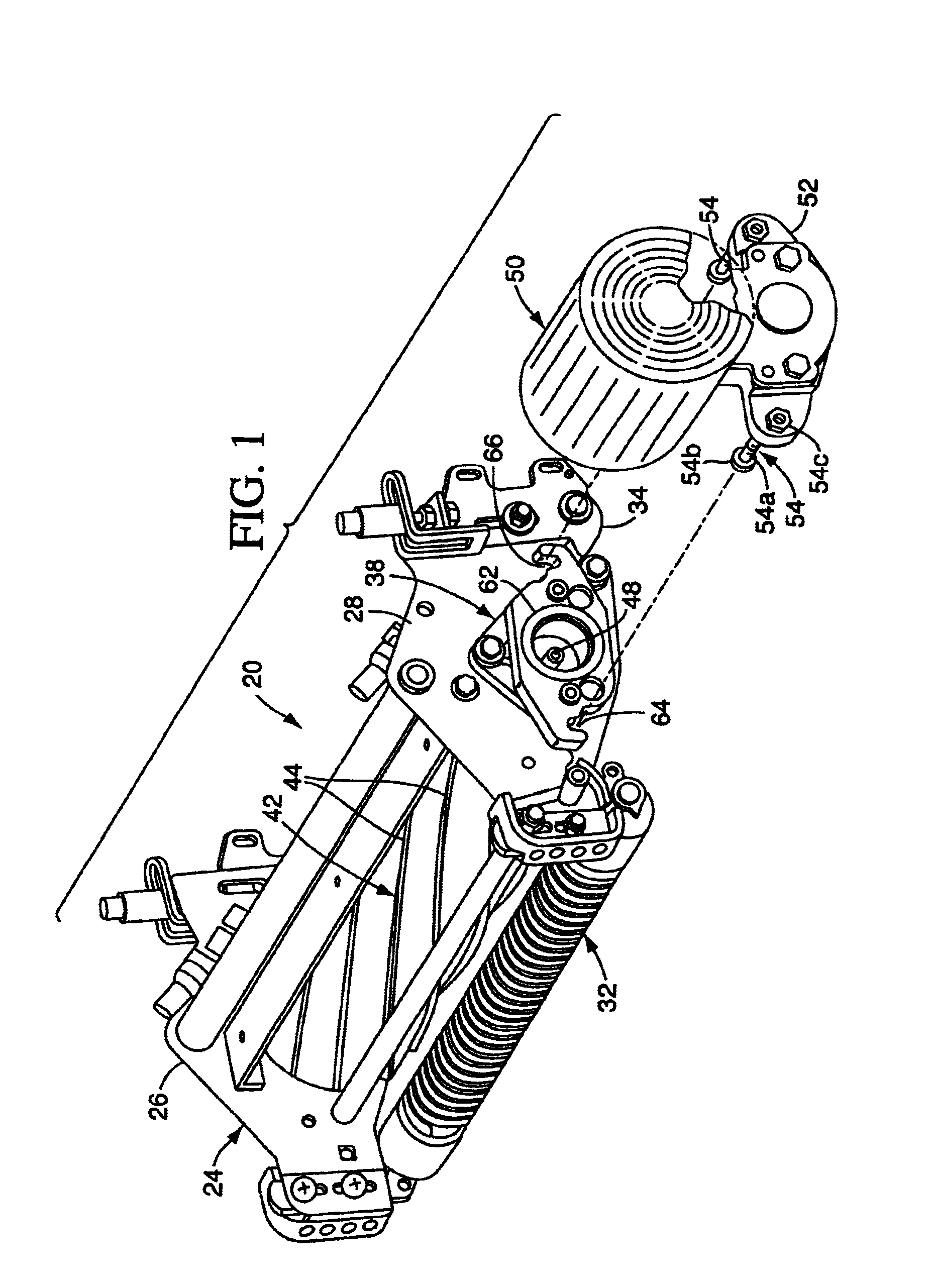
[0028]FIG. 1 illustrates a reel unit 20 of the present invention that is intended to be pulled or pushed by a tractor or other vehicle. Typical known vehicles and cutting reel units are disclosed for example in U.S. Pat. Nos. 5,343,680; 5,412,931 and 5,459,984.

[0029]The reel unit 20 illustrated includes a support frame 24 that includes sideplate 26, 28. The sideplate 26, 28 are supported by front and rear rollers 32, 34 respectively. The sideplates 26, 28 each carry a reel housing 38 (one shown). A reel 42 (shown schematically) having blades 44, is rotatably carried by the two housings 38. The re...


PUM


Abstract

The invention provides an electric motor drive for a reel mower. The drive includes an electric motor, a casing, an endless traction member and a secondary output shaft. Preferably the electric motor is a brush-less permanent magnet type electric motor. The electric motor includes a rotor, a stator, and a motor housing that carries the rotor and stator, the rotor having a rotor output shaft extending from the housing. The casing is mounted to the motor housing. The endless traction member is engaged to the rotor output shaft to be circulated by rotation of the rotor output shaft. The secondary output shaft is engaged by the endless traction member to be rotated by circulation of the endless traction member. The secondary output shaft extends from inside the casing to outside the casing to be operatively connected to the reel to rotate the reel. The secondary output shaft is mounted at about the same elevation as the axis of rotation of the reel and the rotor output shaft is mounted above the axis of rotation of the reel.

Description

TECHNICAL FIELD OF THE INVENTION[0001]The invention relates to electric motor drives for reel mowers. Particularly, the invention relates to an electric motor assembly and mounting arrangement on a reel mower.BACKGROUND OF THE INVENTION[0002]Conventional reel mowers have been known that utilize hydraulically driven motors, brush-less permanent magnet motors or commutated electric motors to drive the reel. Hydraulically driven motors and brush-less permanent magnet motors have been known wherein the motors directly drive the reel. Commutated electric motors have been known which are located above the reel, centrally located, and which drive the reel with a belt.[0003]The present inventors have recognized that it would be desirable to provide a brush-less permanent magnet motor drive for a reel mower which drove the reel mower via a belt. The present inventors have recognized that it would be desirable to provide a brush-less permanent magnet drive for a reel mower wherein the brush-l...

Claims


Application Information

Patent Timeline
Patent Type & Authority Patents(United States)
IPC IPC(8): A01D34/47A01D34/412H02K7/10H02K7/116
CPCA01D34/475H02K7/116H02K7/1004
Inventor RINHOLM, BRENT GORDONGRIFFIN, RANDALL JOHN
Owner DEERE & CO
Learn More