
Light chamber for door for gaming machine

Inactive Publication Date: 2005-09-20
ARISTOCRAT TECH AUSTRALIA PTY LTD
View PDF9 Cites 8 Cited by
  • Summary
  • Abstract
  • Description
  • Claims
  • Application Information

AI Technical Summary

Problems solved by technology

One problem which arises is that the bill acceptor depends down from the shelf behind the belly door and this prevents a horizontally mounted fluorescent light tube from extending from one horizontal end of the artwork to the other horizontal end.
Because it is not possible to light the artwork between the artwork and the bill acceptor, there is typically a shadow behind the artwork where the bill acceptor is positioned.
However, this still produces uneven lighting and in particular, produces “hot spots” which are more backlit than other areas of the artwork.
It is a difficult and fiddly process to pivot the chamber, disconnect and remove the fluorescent light and replace it with another tube.

Method used


Image

  • Light chamber for door for gaming machine
  • Light chamber for door for gaming machine
  • Light chamber for door for gaming machine

Examples


Embodiment Construction

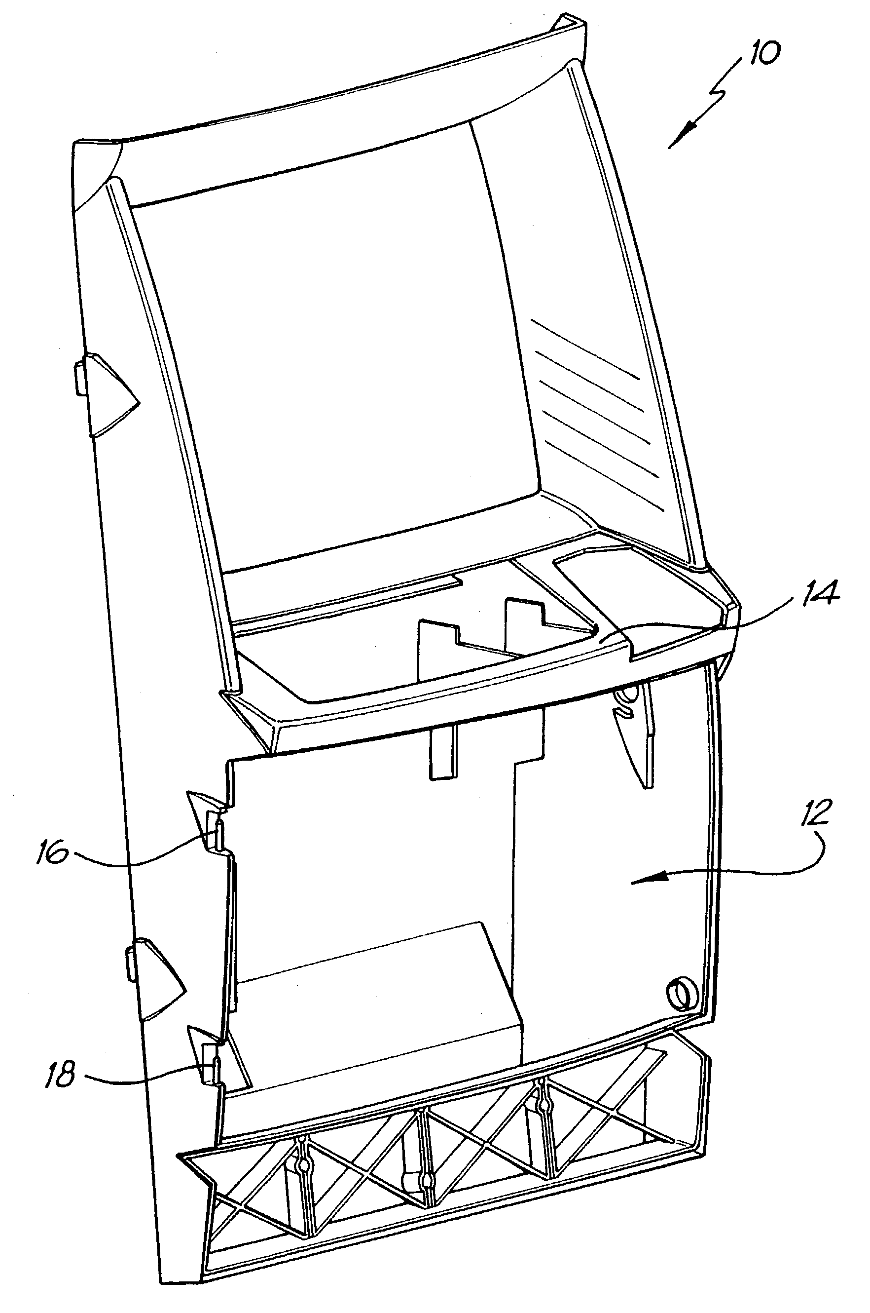
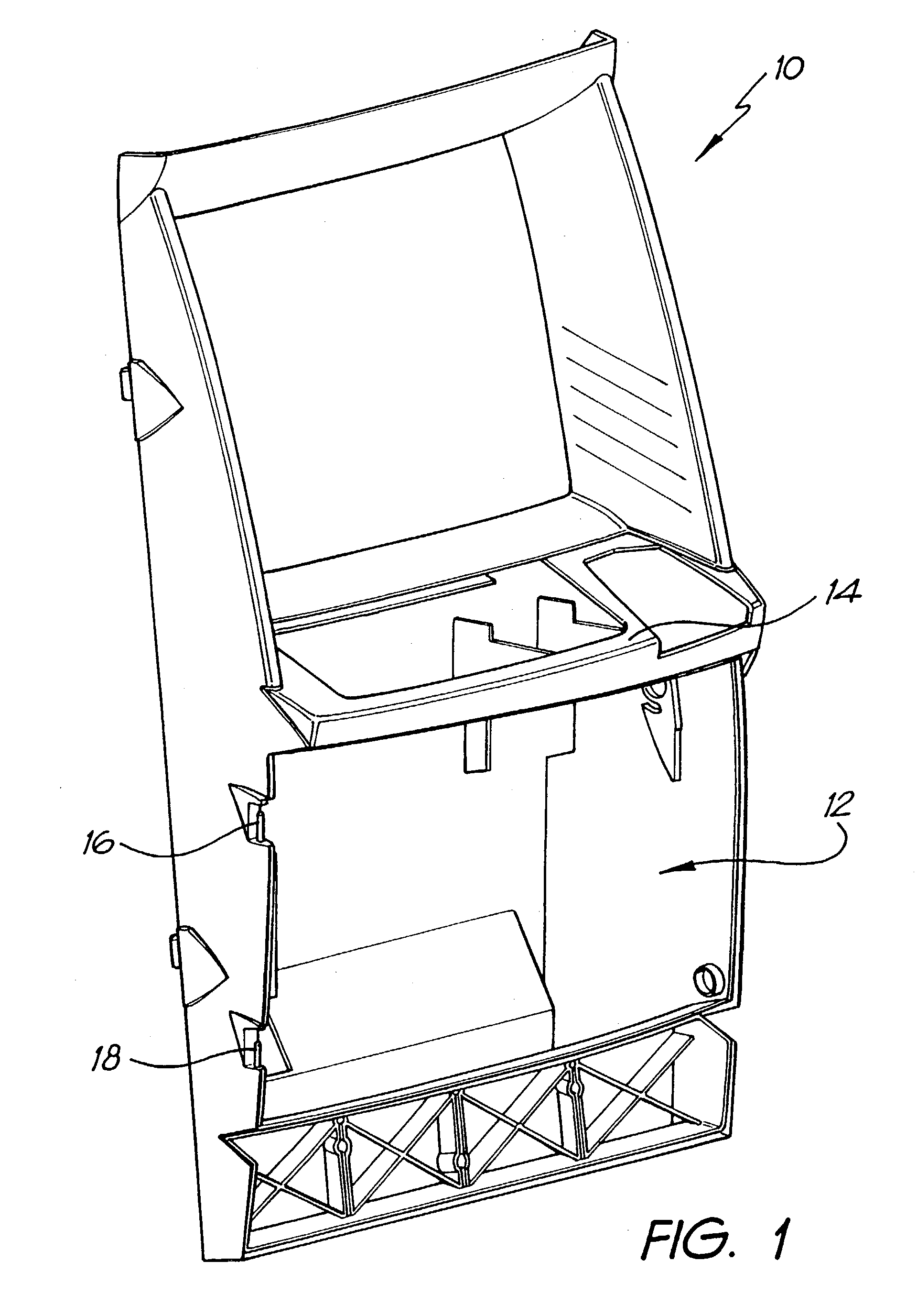
[0029]Referring to the drawings. FIG. 1 shows a main door 10 for a gaming machine. The basic door 10 is shown before trim and other components are fitted. The door has an aperture 12 located below a shelf 14 on which control buttons are located on the finished door. The aperture is openable and closeable by a door known as a “belly door” (not shown in FIG. 1). The components of the belly door are shown in FIGS. 2 to 6. The belly door is mounted to the main door on two upstanding hinge pins 16, 18 disposed on one side of the aperture 12 of the door.

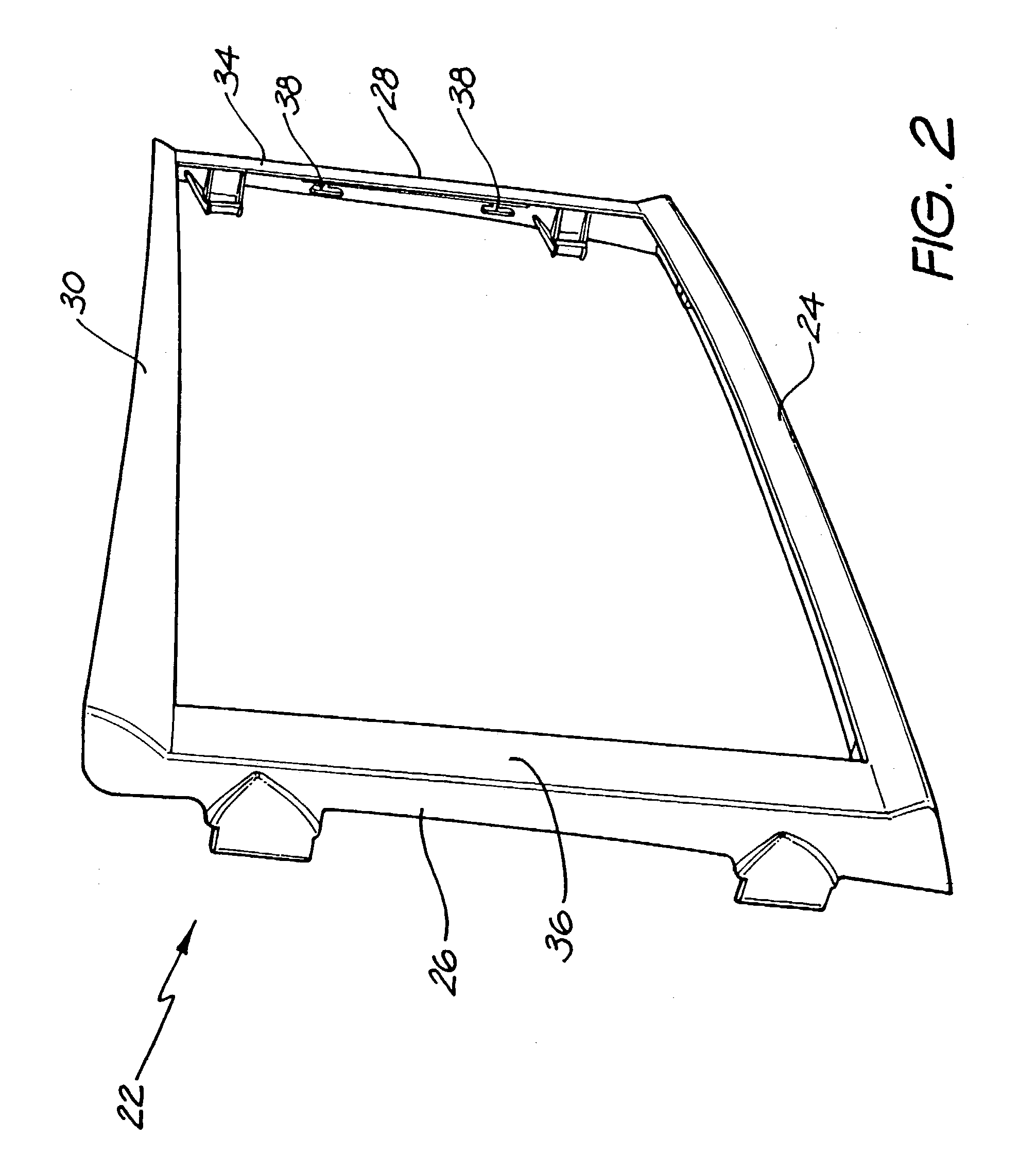
[0030]The belly door includes two main components, a light chamber 20 shown in FIGS. 4 and 5 and an outer frame 22 which is shown in FIGS. 2 and 3. The frame comprises a base member 24, two side members 26, 28 and a top member 30. As is best seen in FIG. 3, a curved wall 32 extends along the front of the base member. A similar wall (not shown) depends downwardly from the top member of the frame. When viewed from the front of the belly door...


PUM


Abstract

A belly door for a gaming machine includes a frame for receiving a sheet of artwork and a light reflective chamber having an open face which is located behind the frame when in a closed position. Clamping means are provided for clamping the artwork between the frame and the chamber. A recess extends along one edge of the chamber including sockets for receiving a fluorescent light tube when the chamber is in the closed position. A diffuser panel is disposed in the chamber behind the artwork located so as to be edge lit by the fluorescent light tube. The reverse face of the panel, which in use, faces the rear wall of the chamber defines a series of white opaque dots which in use, diffuse and direct the light in a forward direction perpendicular to the plane of the panel. The size of the dots in the panel increases with the distance of the dots from the fluorescent light tube. This arrangement ensures that the light panel produces a very evenly balanced lighting of the artwork.

Description

CROSS-REFERENCE TO RELATED APPLICATIONS[0001]This application is a National Phase application of PCT / AU00 / 01369 filed on Nov. 8, 2000, the disclosure of which is incorporated herein by reference in its entirety and claims the benefit of the Australian application PQ 3989 filed November 11, 1999, and is related to and filed concurrently with application Ser. No. 10 / 130,172, which is a National Phase Application of PCT. Application no. PCT / 00 / 01371.FIELD OF THE INVENTION[0002]This invention relates to gaming machines also referred to as slot machines, fruit machines or poker machines and in particular, it relates to a light chamber assembly for such as a gaming machine.BACKGROUND OF THE INVENTION[0003]A typical upright gaming machine comprises a cabinet and a main door which swings open on hinges to allow access to the interior of the cabinet. The main door may extend almost the entire length of the cabinet from its top to its bottom. In the middle of the door, there is usually a shel...

Claims


Application Information

Patent Timeline
IPC IPC(8): A63F13/08A63F13/90
CPCA63F13/08A63F13/90G07F17/32
Inventor SOKOLOV, RICHARDD'SOUZA, ERROLHALIC, VLADIMIRJOHNSON, IAN FREDERICK
Owner ARISTOCRAT TECH AUSTRALIA PTY LTD
Learn More