
Refrigerant cycle with defrost termination control

a technology of defrost termination and refrigerant cycle, which is applied in the direction of defrosting, domestic cooling apparatus, etc., can solve the problems of flooding in the evaporator and compressor, and do some damage to goods within the spa

Active Publication Date: 2005-09-20
CARRIER CORP
View PDF5 Cites 7 Cited by
  • Summary
  • Abstract
  • Description
  • Claims
  • Application Information

AI Technical Summary

Problems solved by technology

Especially in refrigeration applications, the fan would carry the liquid water with the air and could do some damage to goods within the space to be conditioned.
There are problems with the above prior art method of operation.
This increased refrigerant flow could lead to flooding in the evaporator and compressor, which is undesirable.

Method used


Image

  • Refrigerant cycle with defrost termination control
  • Refrigerant cycle with defrost termination control

Examples


Embodiment Construction

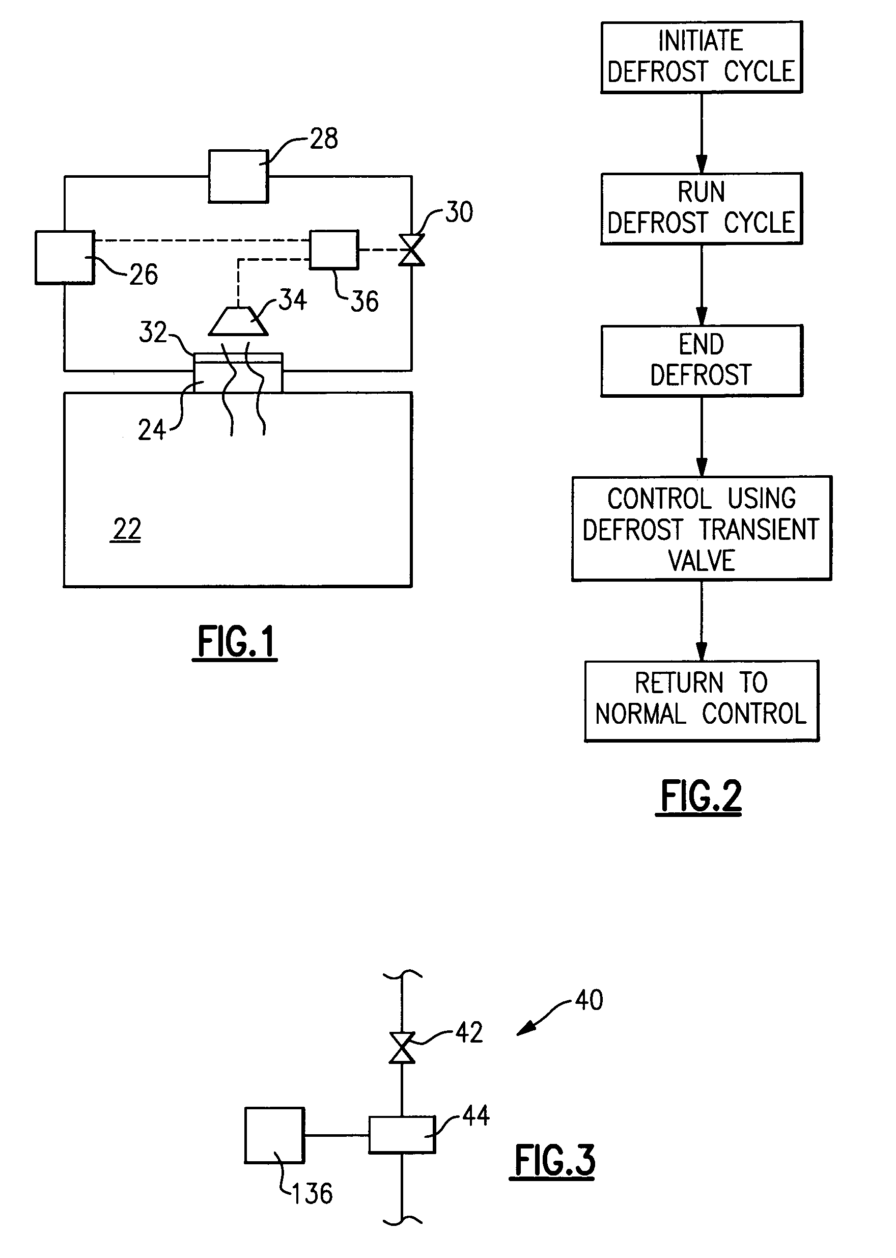
[0013]A refrigerant cycle 20 is illustrated in FIG. 1 for conditioning an environment 22. Environment 22 may be a refrigerated chamber, or any other environment to be cooled. An evaporator 24 is positioned to condition the air within the environment 22. Downstream of the evaporator 24 is a compressor 26. A condenser 28 is positioned downstream of the compressor 26, and an expansion device 30 is positioned downstream of the condenser 28. As shown, a heater element 32 is associated with the evaporator 24. An air handler or fan 34 passes air over the evaporator 24 and into the environment 22.

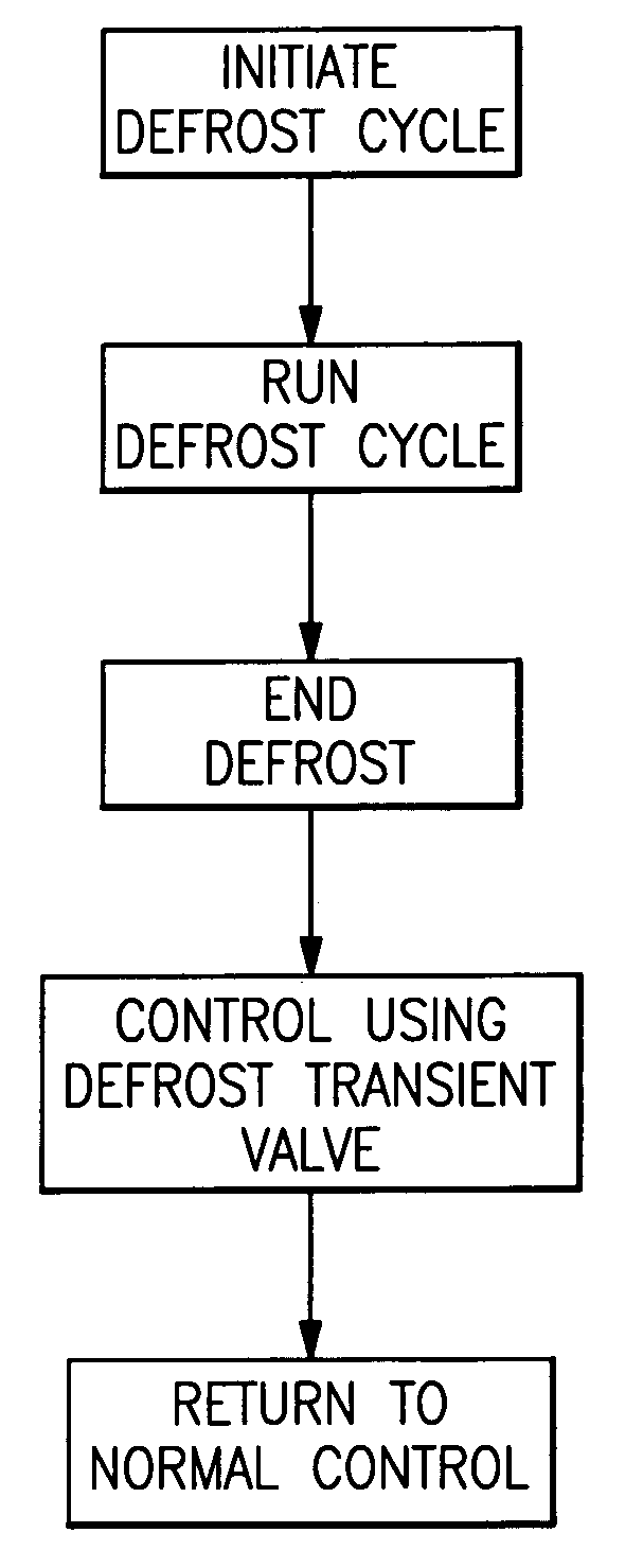
[0014]A control 36 controls the compressor 26, the fan 34, the heater element 32 and the expansion device 30 in a first embodiment. When it is determined that a defrost cycle is desirable, the compressor 26 and fan 34 are stopped. The heater 32 is initiated, and the coils of the evaporator 24 are defrosted. At the end of a predetermined period of time, the defrost cycle is ended. At that time, the ...


PUM


Abstract

A refrigerant cycle is provided with a transient mode for moving from a defrost cycle back to steady state operation. In particular, some default position of the expansion device is selected when defrost cycle ends. The evaporator is hot at the end of defrost cycle, and might otherwise suggest an increased flow of refrigerant through the expansion device, which could be undesirable. Thus, a control for the inventive system moves the expansion device to a defrost transient position, with the defrost transient position restricting the flow of refrigerant to a value that would be less than that dictated by the high temperature of the evaporator. At some period of time after the end of the defrost mode, the refrigerant cycle can be returned to state steady operation.

Description

BACKGROUND OF THE INVENTION[0001]This invention relates to a control algorithm for moving from the end of a defrost transient back to steady state operation in a refrigerant cycle.[0002]Refrigerant cycles are utilized to provide cooling, such as for refrigerant systems, or air conditioning systems. In a typical refrigerant cycle, a compressor compresses a refrigerant and delivers a hot refrigerant to a downstream condenser, which is typically located outside. From the condenser, the refrigerant passes to an expansion device at which the refrigerant is expanded and cooled. The cool refrigerant then passes into an indoor heat exchanger known as an evaporator. A fan typically passes air over the evaporator, and the air is cooled by the refrigerant. This cooled air is then passed into an environment to be conditioned.[0003]In a standard air conditioning application, this air is brought to a temperature that is comfortable for human occupation. In refrigeration applications, the air is b...

Claims


Application Information

Patent Timeline
Patent Type & Authority Patents(United States)
IPC IPC(8): F25D21/08F25D21/00
CPCF25D21/006F25D21/08F25B2500/06F25B2600/0251F25B2600/112F25B2600/23F25B2600/2513Y02B30/743Y02B30/70
Inventor REASON, JOHNNADER, AWWAD
Owner CARRIER CORP
Learn More