
Virtual print driver system and method

a printer and driver technology, applied in the field of multi-printer, can solve the problems of loss of error handling and/or job completion notices, user is unconcerned with selecting from a plurality of printers or printing devices, and method requires a large amount of network traffi

Inactive Publication Date: 2005-09-13
PATOIS TELECOM LIMITED LIABILITY
View PDF5 Cites 75 Cited by
  • Summary
  • Abstract
  • Description
  • Claims
  • Application Information

AI Technical Summary

Benefits of technology

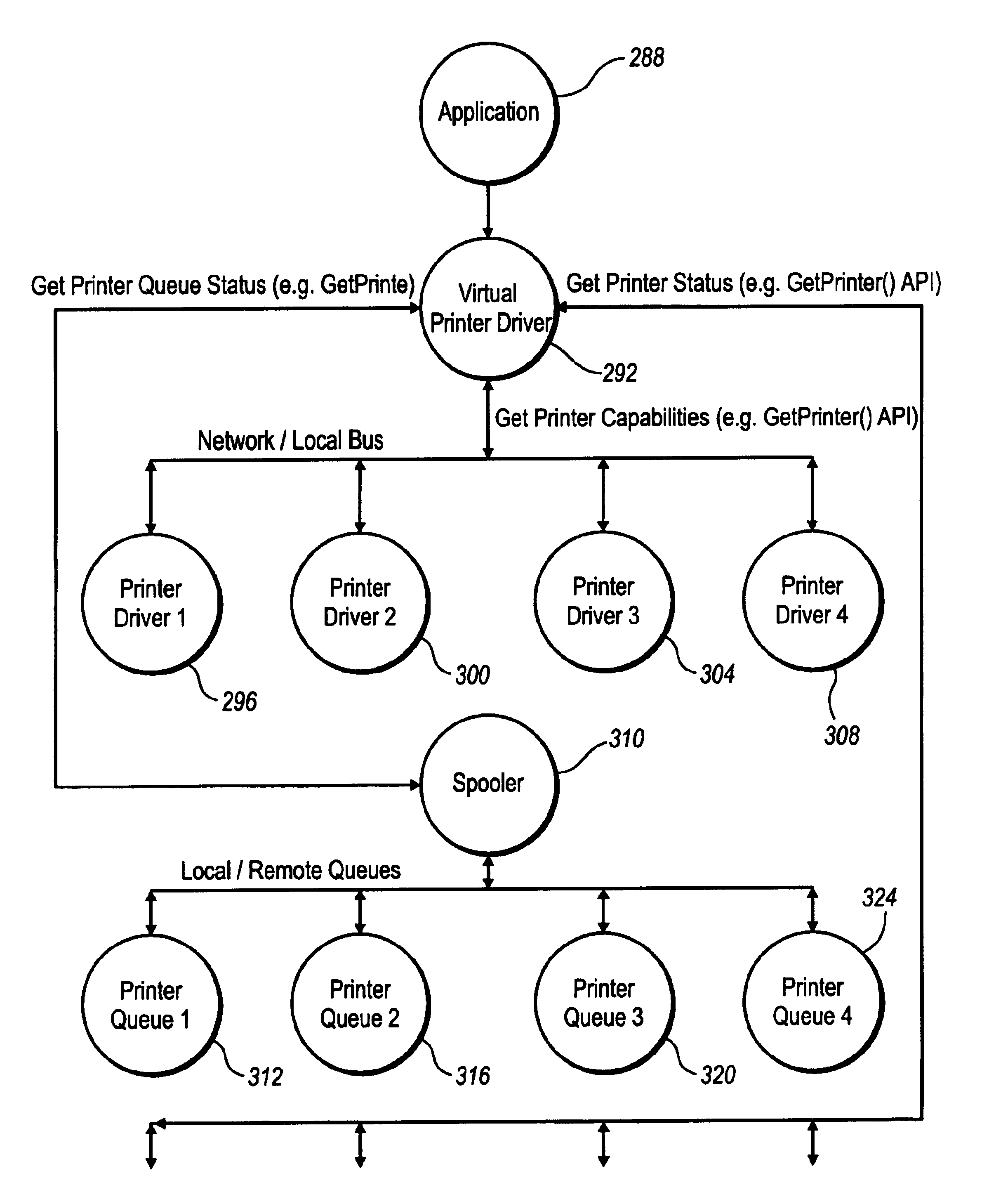
"The present invention provides a computer-based printing system and method that allows a user to select the best printer amongst a list of available printers based on factors such as the ability of the client computing device to assemble and render the print job, the quality of the output, the availability of one or more printing devices, and the locality of the printing device. The virtual printer driver allows for a seamless selection process, providing advantages such as using only a single dialog selection to carry out the print job, allowing sheet assembly emulation, and being supportable within a local, networked, or remote printing environment. The invention overcomes the limitations of prior art printing systems and improves the printing experience."

Problems solved by technology

In this basic setup, the User is unconcerned with selecting from a plurality of printers or printing devices because the system simply has only one printer accessible from client computing device.
While this method for network printing enables a variety of client computer devices to utilize a network printer device, the method requires a large amount of network traffic since the print data must be de-spooled twice over the network, once to the printer server from the printing source, and once to the printing device(s) from the printer server.
Furthermore, the traditional method causes a loss of bi-directional communication, resulting in a loss of error handling and / or a loss of job completion notices.
Moreover, the traditional method requires the use of an additional computer device (the print server), which causes an increase in hardware costs and maintenance.
These methods cause the client computer device to consume CPU cycles and / or generate additional network traffic.
Furthermore, there is no centralized management of the print jobs and thus no prioritization.
However, this attempt requires a copy of the corresponding printer driver to be located on the print server, further requiring the maintenance and / or licensing of an extra printer driver.
Moreover, this attempt does not address the loss of bi-directional communication or the requirement of an additional computer device, the print server.
Moreover, the print server consumes additional CPU cycles to render the journal data into printer ready data.
While allowing some degree of flexibility, this type of limited process and / or approach suffers in that the User must either have prior knowledge of the capabilities of each printer accessible from the client computing device prior to making any final determination or selection of printers, or alternatively, the User must manually select and examine (i.e., enumerate) each printer selection to determine each respective printer's capabilities and print quality.
This approach additionally suffers in that the status monitor only provides very limited information, often only the number of print jobs queued or OFFLINE / READY.
Still further, this approach suffers in that the printer driver and status monitor provide no information on the speed (i.e., PPM), or locality (i.e., physical location) of the respective attached printing device(s).
However, this approach suffers in that the invention does not take into account the availability or locality of the printers.
The '120 patent also suffers in that the printer capabilities are predetermined, which, as a result, requires each of the printers to be pre-known to the User prior to choosing a printer and when constructing a Virtual Printer Driver.
Since the printers have to be pre-known, the User is unable take advantage of any “auto-discovery” techniques to dynamically find or select new and existing printers, or make changes in a printers' capabilities, such as modifying sheet assembly characteristics and / or finishing options, etc.
Still further, the '120 patent also suffers in that the disclosed Virtual Printer Driver cannot take advantage of any Print Assist programs that are, or may be inserted, into the print data flow, such as a custom print processor.

Method used


Image

  • Virtual print driver system and method
  • Virtual print driver system and method
  • Virtual print driver system and method

Examples


Embodiment Construction

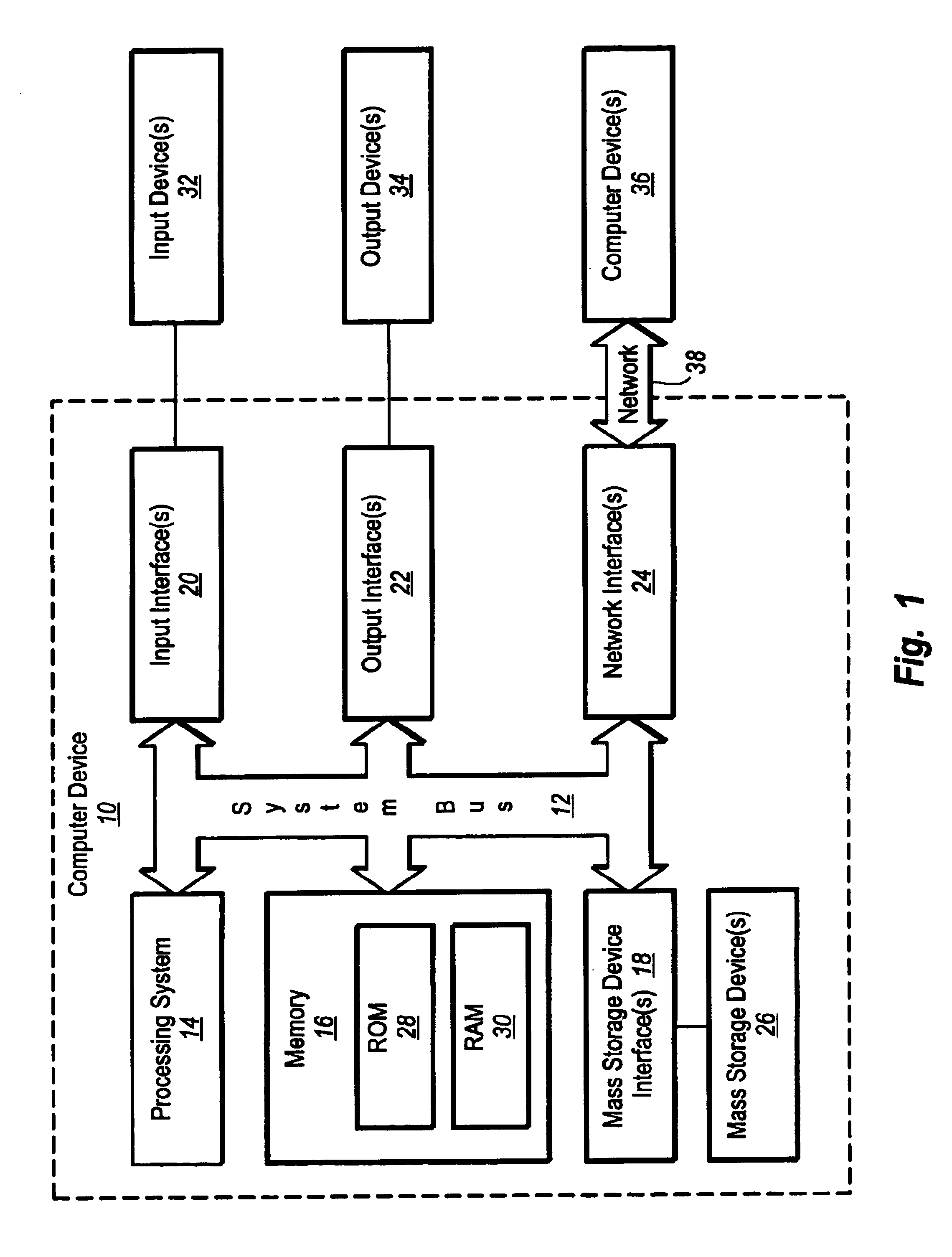
[0034]It will be readily understood that the components of the present invention, as generally described and illustrated in the figures herein, could be arranged and designed in a wide variety of different configurations. Thus, the following more detailed description of the embodiments of the system and method of the present invention, and represented in FIGS. 1 through 7, is not intended to limit the scope of the invention, as claimed, but is merely representative of the presently preferred embodiments of the invention.

[0035]The presently preferred embodiments of the invention will be best understood by reference to the drawings wherein like parts are designated by like numerals throughout.

[0036]The following disclosure of the present invention is grouped into several subheadings. The utilization of the subheadings is for convenience of the reader only and is not to be construed as limiting in any sense.

Exemplary Operating Environment

[0037]FIG. 1 and the corresponding discussion is...


PUM


Abstract

A computer-based printing system, comprised a client computing device, optionally one or more server computing devices, a virtual printer driver, one or more printer drivers, a print processor, print spooler, and one or more printers, means for initiating a print job(s), all or in part, or one or more copies of a document(s), in a local, network or remote, single or multi-user, printing environment, and a means to select the best fit printer based on printer capabilities, print quality and printer availability, without manually enumeration of each printer driver and printer status monitor.

Description

BACKGROUND OF THE INVENTION[0001]1. Field of the Invention[0002]The present invention relates to a multiple printer and associated print environment contained within a local, networked, or remote computing environment. Specifically, the present invention relates to a computer-based printing system having the ability to match a print job contained on one or more printing sources to the “best-fit” printing device contained within a set of available printing devices, wherein the “best-fit” is based on a set of identified criteria.[0003]2. Background and Related Art[0004]With the emergence of software and hardware components of computer systems, users are able to employ the systems to perform a variety of tasks. For example, a user may utilize a software application, such as a word processing, spreadsheet, or other application, to create a file or document. Once created, the document may be printed on a local, network or remote printer device.[0005]In a computer system that includes sim...

Claims


Application Information

Patent Timeline
Patent Type & Authority Patents(United States)
IPC IPC(8): G06F3/12
CPCG06F3/1204G06F3/1226G06F3/126G06F3/1288
Inventor FERLITSCH, ANDREW RODNEY
Owner PATOIS TELECOM LIMITED LIABILITY
Learn More