
Modulated intensity flasher for vehicle brake light with lockout

a technology of vehicle brake light and module, which is applied in the direction of vehicle components, signalling/lighting devices, optical signalling, etc., can solve the problems of lamp being perceived as off and flashing has been primarily limited, and achieve the effect of improving the display indication of the brake of the automobil

Inactive Publication Date: 2005-09-13
WILLIAMS & LAKE
View PDF17 Cites 17 Cited by
  • Summary
  • Abstract
  • Description
  • Claims
  • Application Information

AI Technical Summary

Benefits of technology

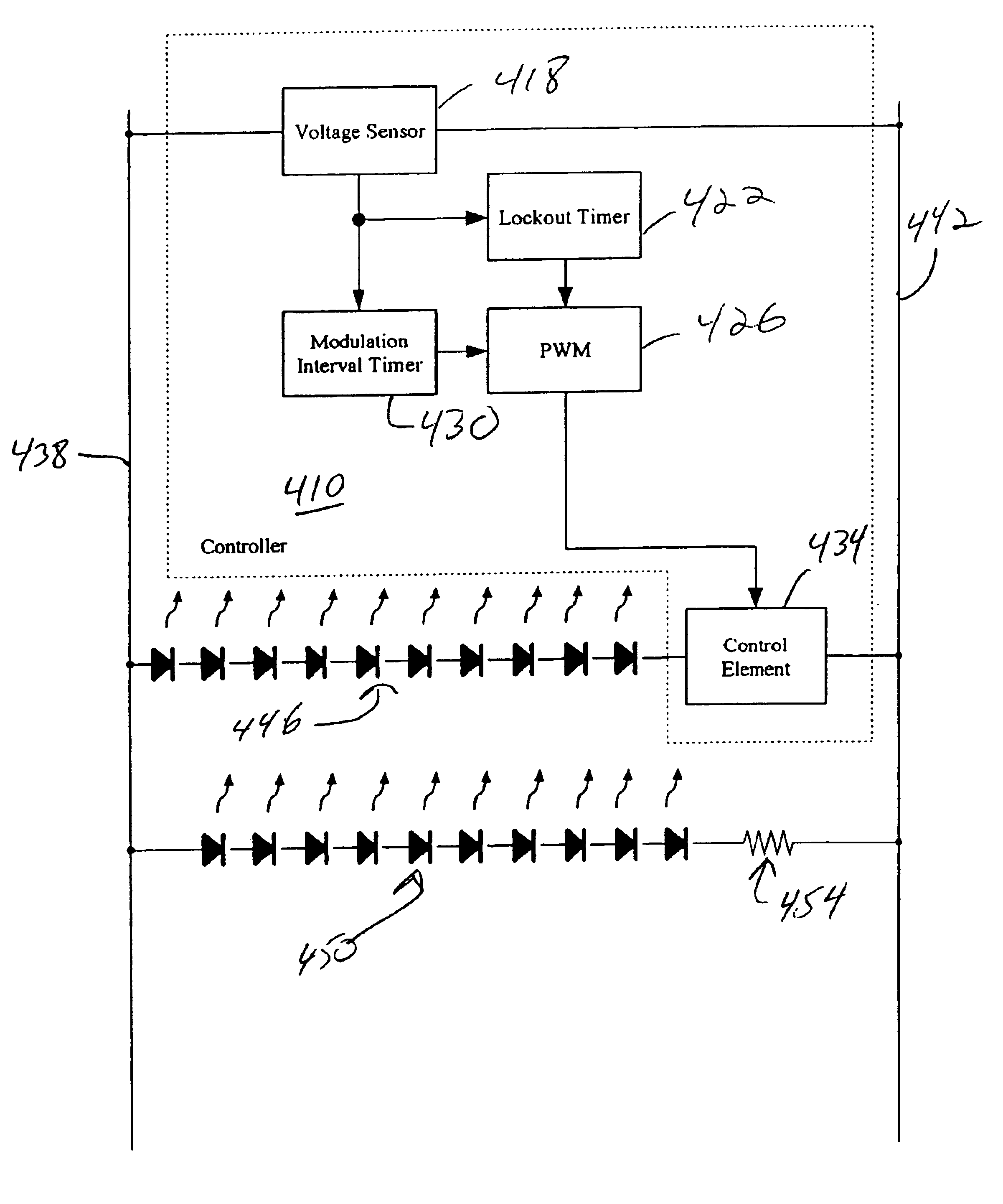
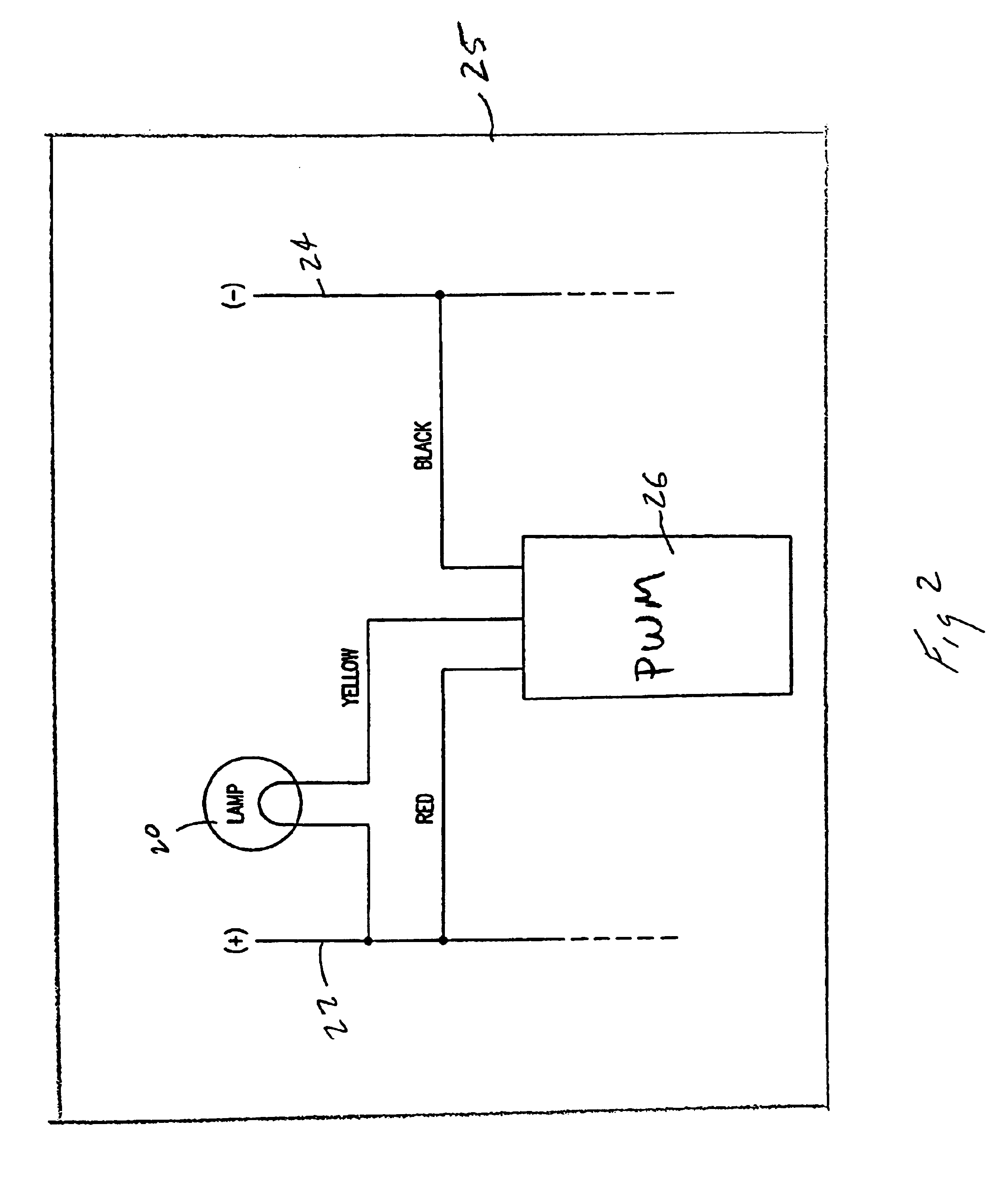
[0010]In accordance with the present invention there is provided a control system for modulating the intensity of a vehicle□s brake light for enhanced display indication of the braking of the automobile. The system includes a modulation unit sized to be disposed within the brake light and interposed electrically between a lamp of the brake light and an energy supply. The unit includes a circuit for sequentially adjusting power from the energy supply to the lamp for a first determined time interval simultaneous with the braking of the automobile for generating a desired intensity flashing of the lamp, while continuously supplying a steady power level to the lamp after expiration of the first timer interval and during continued braking. A lockout timer precludes the flashing of the brake lamp by the unit for a second predetermined time interval after release of the braking for avoiding repetitive flashing in stop-and-go traffic.
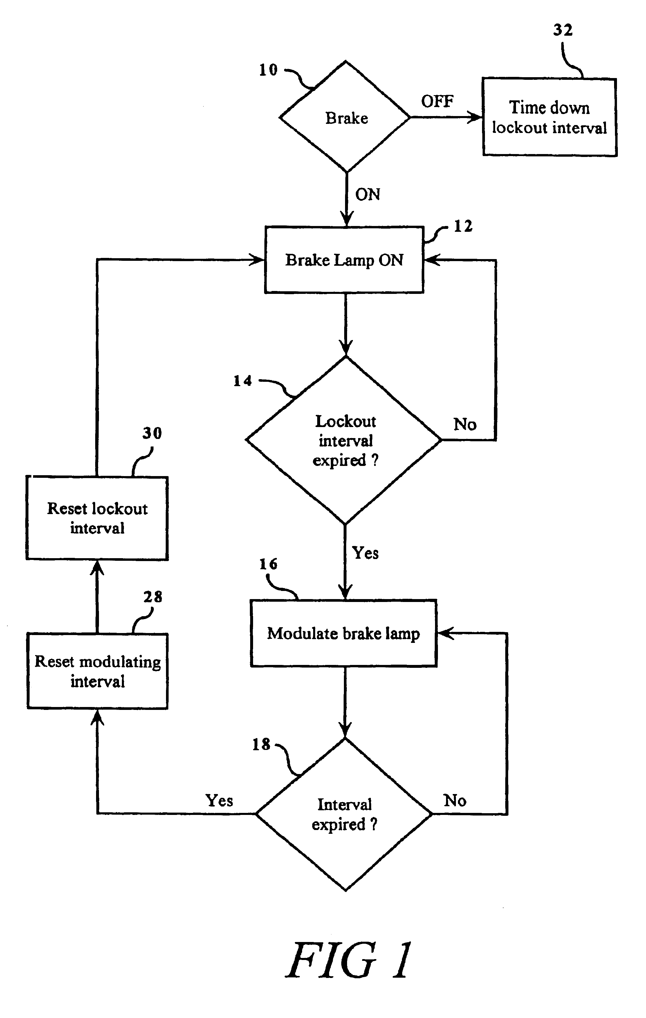
[0013]In accordance with another aspect of the present invention, a method is provided for operating an interval intensity modulator comprising a brake light of a vehicle for improved indication of braking of the vehicle. The method comprises steps of detecting the braking of the vehicle by the transmitting of a supply of energy to the brake light coincident with the braking. The next step comprises sequentially adjusting the supply of energy via a modulator connected to the light for generating a flashing intensity of the light during braking. The time extent of the flashing is detected so that the flashing can be stopped after a preselected time period so that the light will then be continually on during the braking. After the brake is released, a second preselected time period is detected for locking out the flashing to avoid excessive repetitive flashing during stop-and-go traffic.
[0017]One benefit obtained by use of the present invention is a brake unit which provides enhanced indication of the braking of the vehicle.
[0018]Another benefit obtained by the present invention is an intensity flasher which can avoid repetitive, irritating flashing during frequent braking of the vehicle, such as during stop-and-go traffic.

Problems solved by technology

In recent years, design trends have been to make the brake light larger and higher on the vehicle, but flashing has been primarily limited to emergency vehicles.
De-powering a brake lamp during a braking event, so that the lamp is perceived as off, is not desirable for safety reasons, and in some jurisdictions is illegal.

Method used


Image

  • Modulated intensity flasher for vehicle brake light with lockout
  • Modulated intensity flasher for vehicle brake light with lockout
  • Modulated intensity flasher for vehicle brake light with lockout

Examples


Embodiment Construction

[0026]Referring now to the drawings wherein the showings are for purposes of illustrating the preferred embodiments of the invention only, and not for purposes of limiting same, the FIGURES show an interval modulator control with lockout that is particularly useful for adjusting the operation of a vehicle brake light for enhanced display indication of the braking of a vehicle.

[0027]More particularly, and with reference to FIG. 1, the invention provides for the limited modulation of a brake light to signal the braking of a vehicle, but also precludes modulation if the brake is applied more than once within a preset time period to avoid annoying, repetitive flashing of the brake lights. The system will determine if a brake light is on or off by the detection of the supply of current to the brake lamp. Accordingly, as a user hits the brake, the brake lamp will turn on 12. If this is an initial application of the brakes so that it is desired to brighten and dim the unit so adjacent oper...


PUM


Abstract

A method and apparatus for brightening and dimming a brake light of automotive vehicle for enhanced display indication of braking includes a pulse width modulation unit to be electrically connected to a brake lamp for sequentially modulating the supply energy to the lamp to generate a brightening and dimming of the lamp. A time extent of the modulation is detected so that the modulation can be stopped after a preselected time period and the light will be continually on as in a conventional braking operation. After the brake is released by the operator, a second preselected time period for locking out the sequential interrupting is timed down, for avoiding repetitive flashing during stop-and-go traffic.

Description

[0001]This application is a continuation application of U.S. application Ser. No. 10 / 027,093, filed on Dec. 20, 2001, and issuing Apr. 13, 2004 as U.S. Pat. No. 6,720,871, which claims priority from U.S. Provisional Application Ser. No. 60 / 257,324, filed on Dec. 20, 2000.BACKGROUND OF THE INVENTION[0002]This invention pertains to the art of electrical lighting control systems, and more particularly to automotive control systems relating to signaling of a braking of the vehicle via a brake light.[0003]The invention is particularly applicable to either integral assembly or, supplemental addition by kit, of a flasher control unit for a middle brake light of an automobile for enhanced display indication of braking of the vehicle. However, it will be appreciated to those skilled in the art that the invention can be readily adapted for use in other environments as, for example, where similar cautionary signaling is regularly provided, and where in certain circumstances, usually relating t...

Claims


Application Information

Patent Timeline
Patent Type & Authority Patents(United States)
IPC IPC(8): B60Q1/44
CPCB60Q1/444
Inventor BOYER, CLYDE H.STROPKAY, EDWARD J.MORRIS, JR., ROBERT C.
Owner WILLIAMS & LAKE
Learn More