
Multimodality imaging system

a multi-modal imaging and positioning system technology, applied in the field of multi-modal imaging system patient positioning system, can solve the problems of high restrictions on tolerances and mechanical accuracy, cumbersome, time-consuming and tedious tasks, and method has the drawback of being quite expensive, cumbersome, and cumbersom

Inactive Publication Date: 2005-09-06
ELGEMS
View PDF3 Cites 16 Cited by
  • Summary
  • Abstract
  • Description
  • Claims
  • Application Information

AI Technical Summary

Benefits of technology

[0007]The present invention seeks to provide improved apparatus that substantially maintains linear and angular registration between a plurality of imaging systems of a multimodality imaging system.
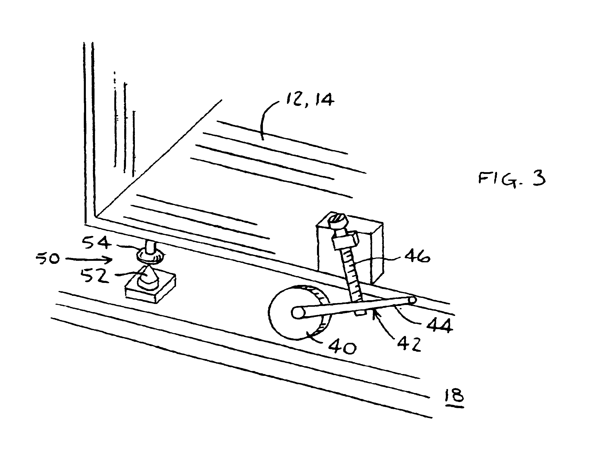
[0008]In the present invention, at least one of the imaging systems is slidingly mounted on a set of one or more rails. The rails may be adjusted linearly along a vertical axis perpendicular to the longitudinal axis of the rails, and adjusted rotationally about a third axis perpendicular to the two aforementioned axes. This provides several advantages. First, mounting one or more of the imaging systems on rails enables separating the imaging systems easily and quickly for servicing. Secondly, after servicing there is generally no need for time-consuming recalibration after re-positioning the displaced imaging system to its original position. Third, since the rails are capable of linear and rotational adjustment, the invention enables quick and straightforward initial calibration and alignment of the imaging systems with each other.

Problems solved by technology

Basically this approach places high restrictions on tolerances and mechanical accuracies during production and assembly of the system.
This method has the drawback of being quite expensive.
This approach is less expensive than the first approach, but still has a disadvantage of being time-consuming.
Both methods have a further disadvantage, in that if it is required to service one or more of the imaging systems, the systems must be re-aligned, which can be a cumbersome, time-consuming and tedious task.

Method used


Image

  • Multimodality imaging system
  • Multimodality imaging system
  • Multimodality imaging system

Examples


Embodiment Construction

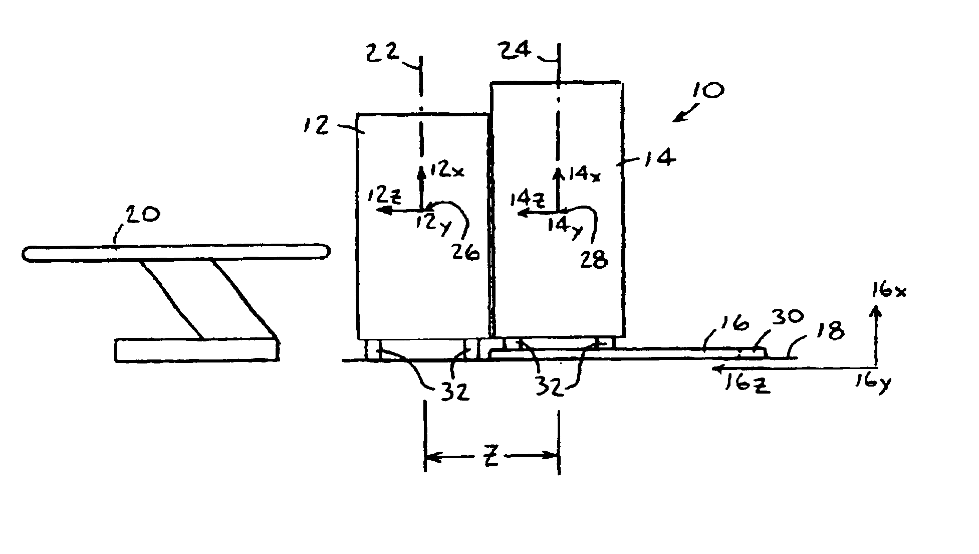
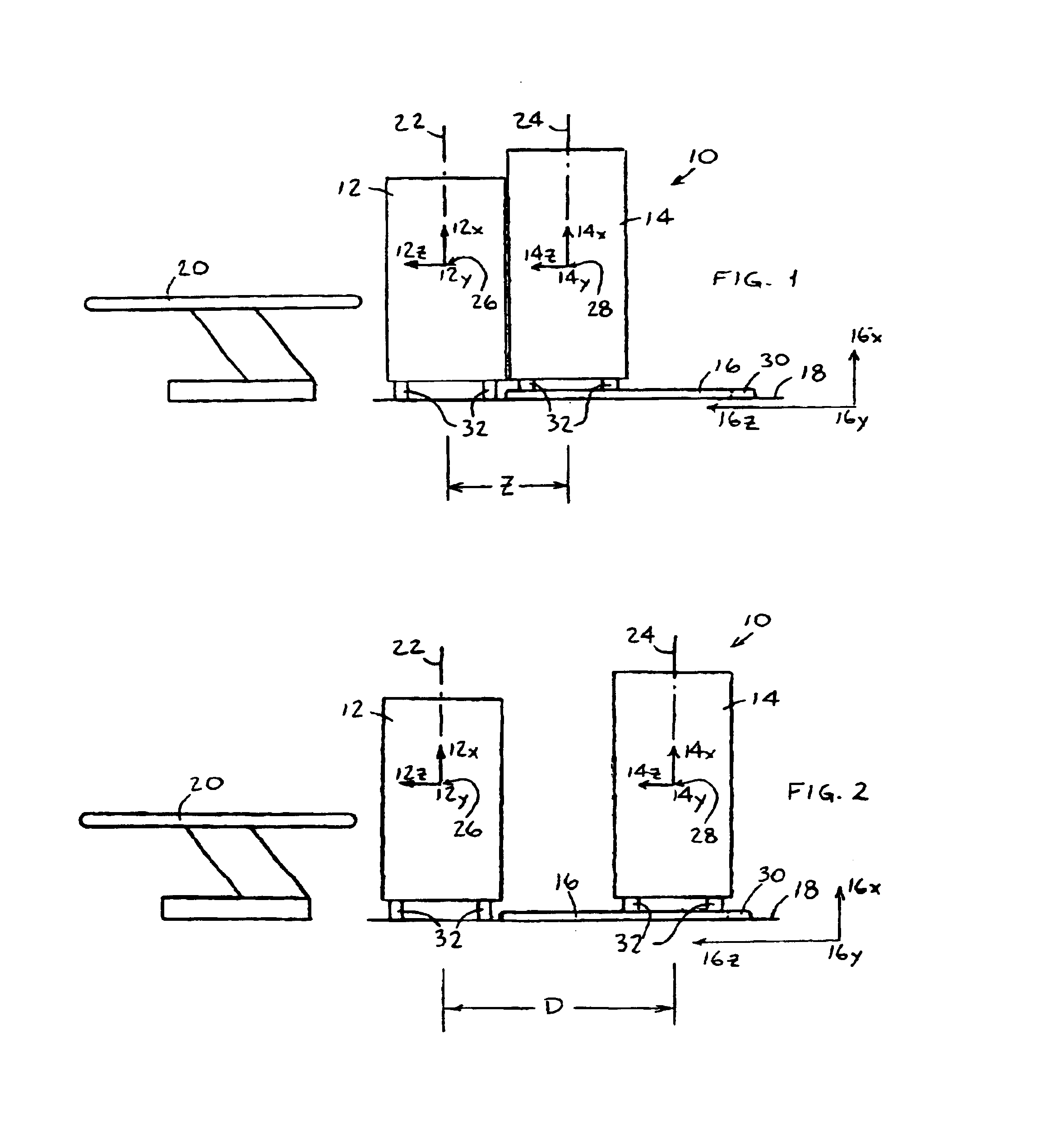
[0027]Reference is now made to FIGS. 1 and 2, which illustrate a multimodality imaging system 10, constructed and operative in accordance with a preferred embodiment of the present invention.

[0028]Multimodality imaging system 10 includes a plurality of imaging systems. In the illustrated embodiment, there is a first imaging system 12, such as a computerized tomography (CT) imaging system, and a second imaging system 14, such as a positron emission tomography (PET) imaging system. One or both of the imaging systems is preferably slidingly mounted on a set of one or more rails 16, fixedly attached to a floor 18. In the illustrated embodiment, there is a pair of generally parallel rails 16, although any other number of rails may be employed to carry out the invention.

[0029]Throughout the specification and claims, “slidingly mounted on one or more rails” is understood to comprise the situation wherein the imaging systems are provided with grooves in which sit the one or more rails, as w...


PUM


Abstract

A multimodality imaging system including a plurality of imaging systems, and at least one rail upon which at least one of the imaging systems is slidingly mounted.

Description

CROSS-REFERENCE TO RELATED APPLICATIONS[0001]This application is a continuation of U.S. patent application Ser. No. 09 / 718,507, now U.S. Pat. No. 6,754,519, filed on Nov. 24, 2000, entitled “Multimodality Imaging System,” and incorporated herein by reference in its entirety.FIELD OF THE INVENTION[0002]The present invention relates generally to patient positioning systems for multimodality imaging systems, and particularly to maintaining linear and angular registration between a plurality of imaging systems of a multimodality imaging system.BACKGROUND OF THE INVENTION[0003]Imaging systems acquire images of a patient, such as images of a suspected tumor, for diagnosis and subsequent treatment or therapy. Commonly used medical imaging systems include fluoroscopy, computerized tomography (CT), magnetic resonance (MRI) or positron emission tomography (PET), for example.[0004]Many imaging systems employ a patient table or couch (the terms being used interchangeably herein throughout the d...

Claims


Application Information

Patent Timeline
IPC IPC(8): A61B6/00
CPCA61B6/032A61B6/037A61B6/584
Inventor HAJAJ, BENNYALTMAN, HERNANSTEINFELD, SERGIOHEFETZ, YARON
Owner ELGEMS
Learn More