
Atrial fibrillation detection method and apparatus

a technology of atrial fibrillation and detection method, which is applied in the field of method and an apparatus can solve the problems of system solely dependent on a hmm methodology, unable to detect atrial fibrillation,

Inactive Publication Date: 2005-08-30
GE MEDICAL SYST INFORMATION TECH
View PDF7 Cites 36 Cited by
  • Summary
  • Abstract
  • Description
  • Claims
  • Application Information

AI Technical Summary

Benefits of technology

[0011]As is apparent from the above, it is an advantage of the present invention to provide an atrial fibrillation detection method and apparatus. Other features and advantages of the present invention will become apparent by consideration of the detailed description and accompanying drawings.
to provide an atrial fibrillation detection method and apparatus. Other features and advantages of the present invention will become apparent by consideration of the detailed description and accompanying drawings.

Problems solved by technology

In more severe cases, AF can lead to a fatal medical condition.
However, these types of systems can, in general, only suggest that an irregular rhythm may be caused by atrial fibrillation.
While the EKpro product is better than many others in predicting an AF condition, it still suffers from the problem of relying solely on ventricular data, and is dependent upon the data used to train it.
Since such data sets are often difficult to compile, a system solely dependent on a HMM methodology can be biased.
Another difficulty with present systems is that many are not, in general, able to specifically identify AF over other irregular rhythms.
The inability to specifically identify the exact irregular rhythm suffered by the patient is problematic in hospital environments, where most patient monitoring is alarm-based.
If there are too many false alarms, the medical professional may become desensitized, responding slowly or lackadaisically to alarms.
This may cause a professional to respond inadequately when a severe or critical condition occurs.

Method used


Image

  • Atrial fibrillation detection method and apparatus
  • Atrial fibrillation detection method and apparatus
  • Atrial fibrillation detection method and apparatus

Examples


Embodiment Construction

[0020]Before one embodiment of the invention is explained in detail, it is to be understood that the invention is not limited in its application to the details of the construction and the arrangements of the components set forth in the following description or illustrated in the drawings. The invention is capable of other embodiments and of being practiced or being carried out in various ways. Also, it is to be understood that the phraseology and terminology used herein is for the purpose of description and should not be regarded as limiting.

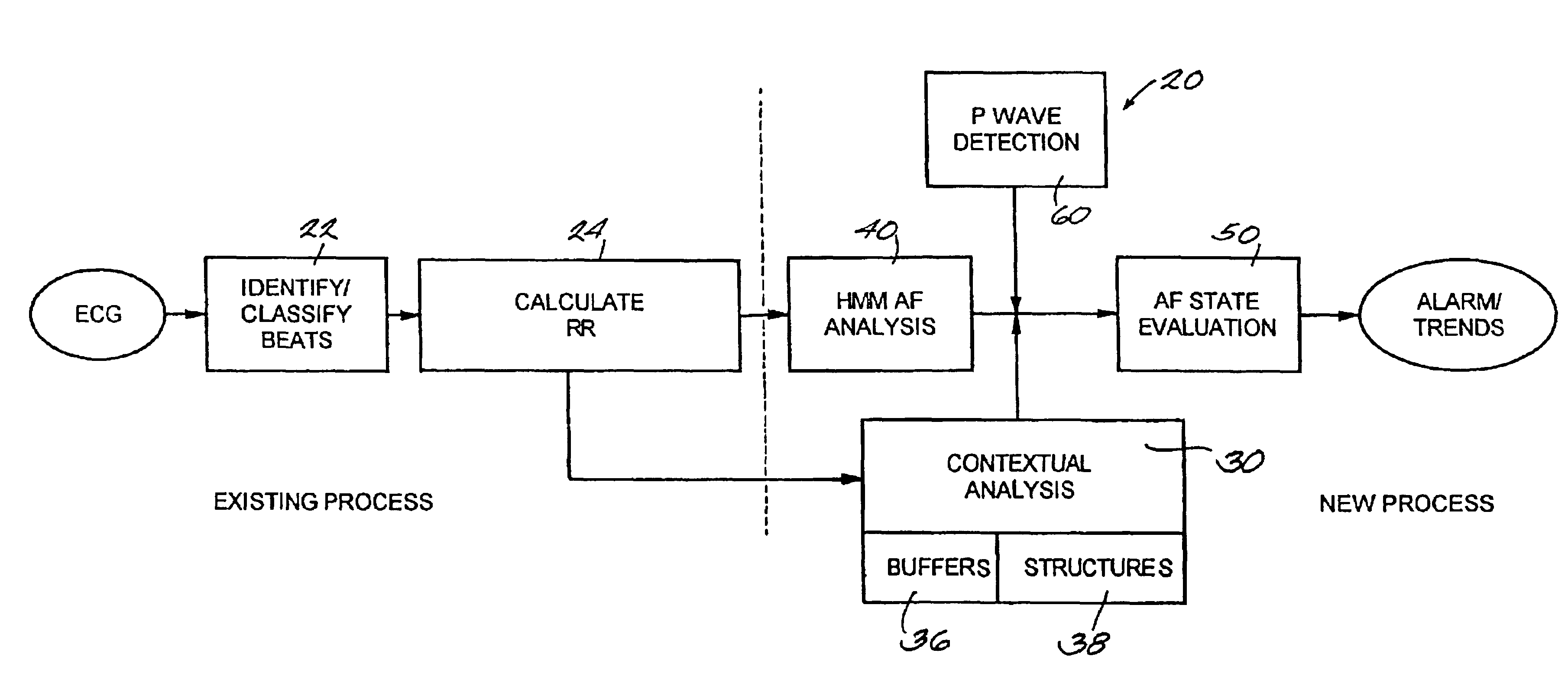
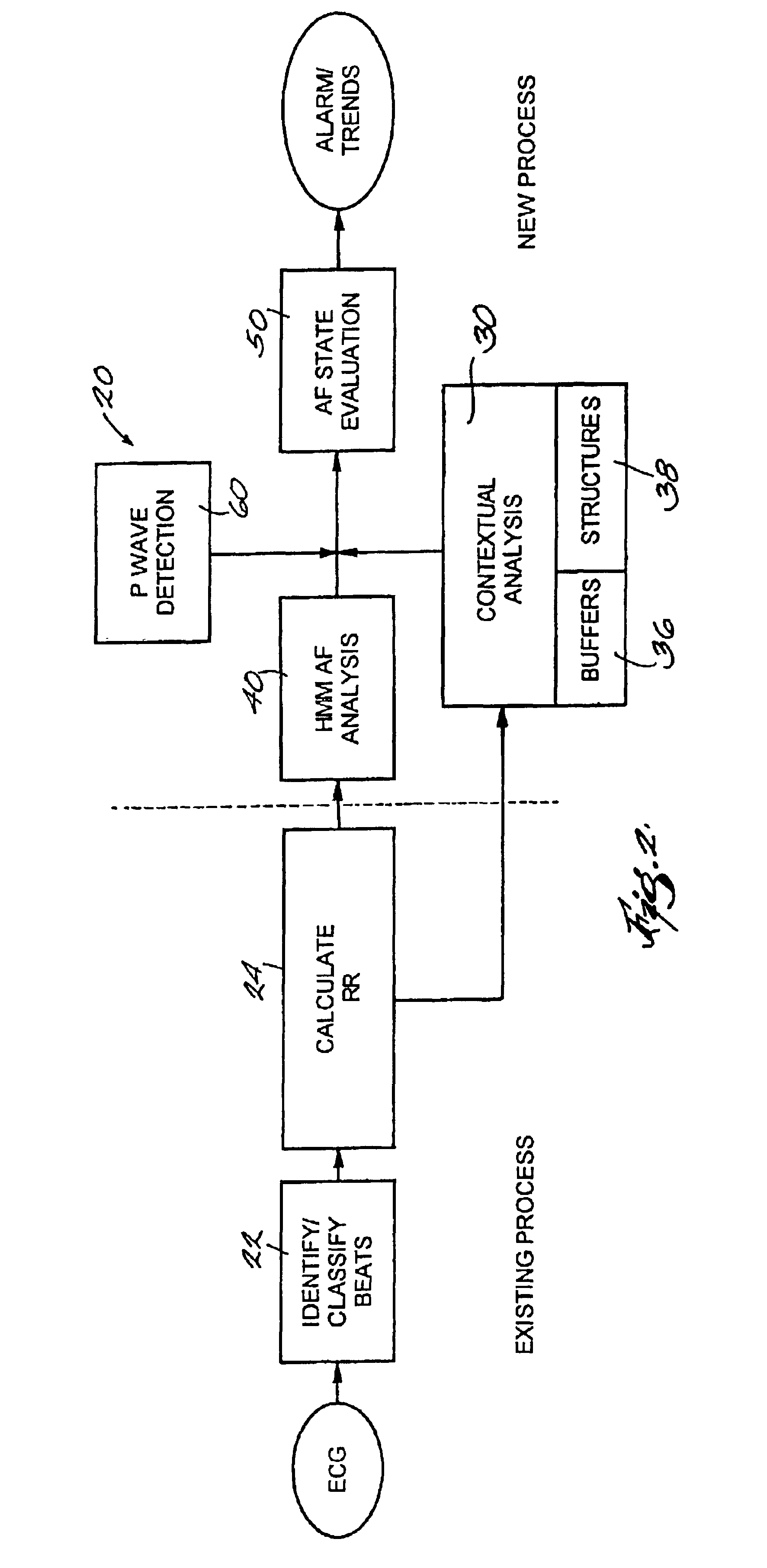
[0021]A system 20 embodying the invention is shown in FIG. 2. As should be apparent to those of ordinary skill in the art, the invention is intended to be implemented in software running on a computer or similar device capable of executing instructions and having such common hardware components as a central processor, memory, and input and output devices as well as software components such as an operating system and graphical interface, which of...


PUM


Abstract

A method and apparatus to detect irregular heart activity and estimate heart rate. In one embodiment, the heart rate estimation apparatus includes a group of six RR storage structures that receives an input of six successive RR interval values. The apparatus also includes a probability engine coupled to the group of RR storage structures, the probability engine is operable to calculate and output a mean value of the six RR interval values and a median value of the mean value and the six RR interval. In one embodiment, the apparatus carries out a method including the acts of determining a plurality of interval values between successive R waves; determining a mean of a group of six interval values; determining a median interval value for a group including the group of six interval values and the mean of the group of six interval values; and determining a running average of interval values between successive R waves using the median interval value.

Description

RELATED APPLICATIONS[0001]The present application is a continuation of U.S. patent application Ser. No. 09 / 750,846 filed Dec. 28, 2000, now U.S. Pat. No. 6,490,479 and is hereby incorporated by reference herein.BACKGROUND OF THE INVENTION[0002]The present invention relates to methods and devices used to detect irregularities in the beating of an animal heart, generally known as “arrhythmias.” More particularly, the invention relates to a method and an apparatus to detect atrial fibrillation (“AF”).[0003]As is well known in the medical field, the contraction of an animal heart is controlled by a series of electrical signals that originate in the sinus node of the right atrium. These signals can be recorded and the record can be used as a diagnostic and treatment tool. An electrocardiogram (“ECG”) is a graphic display of the electrical signals that cause the heart to contract. A representative ECG waveform 10 is shown in FIG. 1. The ECG 10 includes a number of crests (generally referr...

Claims


Application Information

Patent Timeline
IPC IPC(8): A61B5/046A61B5/0452A61B5/361
CPCA61B5/02405A61B5/046A61B5/7264G16H50/20A61B5/361
Inventor BOCK, ELIZABETH ANNE
Owner GE MEDICAL SYST INFORMATION TECH
Learn More