
Bypass recloser assembly

a technology of recloser and assembly, which is applied in the direction of circuit breaking switch, circuit breaking switch for excess current, hot stick switch, etc., can solve the problems of line short circuit, more difficult and time-consuming installation, and prone to deterioration of electrical wires, so as to reduce the number of parts required, quick and easy installation, and reduce the need for parts inventory

Inactive Publication Date: 2005-08-30
HUBBELL INC
View PDF19 Cites 11 Cited by
  • Summary
  • Abstract
  • Description
  • Claims
  • Application Information

AI Technical Summary

Benefits of technology

The present invention provides an improved bypass recloser assembly that is directly connected to the bypass switch assembly, without the need for electrical wires. The assembly is quick and easy to install and reduces the number of parts required for installation. The technical effects of the invention include improved reliability, reduced installation time and cost, and improved performance.

Problems solved by technology

Additionally, objects may fall across exposed wires, arcing could occur, or other transitory events, such as lightning, could cause momentary power line short circuits or current surges that could bum out a fuse or trip a circuit breaker.
The recloser assemblies are mounted separately from the bypass switch assemblies, thereby causing a more difficult and time consuming installation.
However, the electrical wires are prone to deteriorate over time due to stress caused by the elements, or other causes, such as birds, vandalism or shifting of the recloser assembly and the bypass switch assembly relative to one another.

Method used


Image

  • Bypass recloser assembly
  • Bypass recloser assembly
  • Bypass recloser assembly

Examples


Embodiment Construction

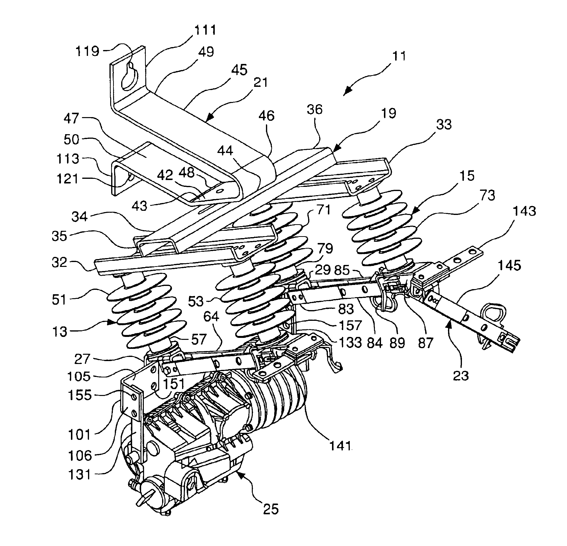
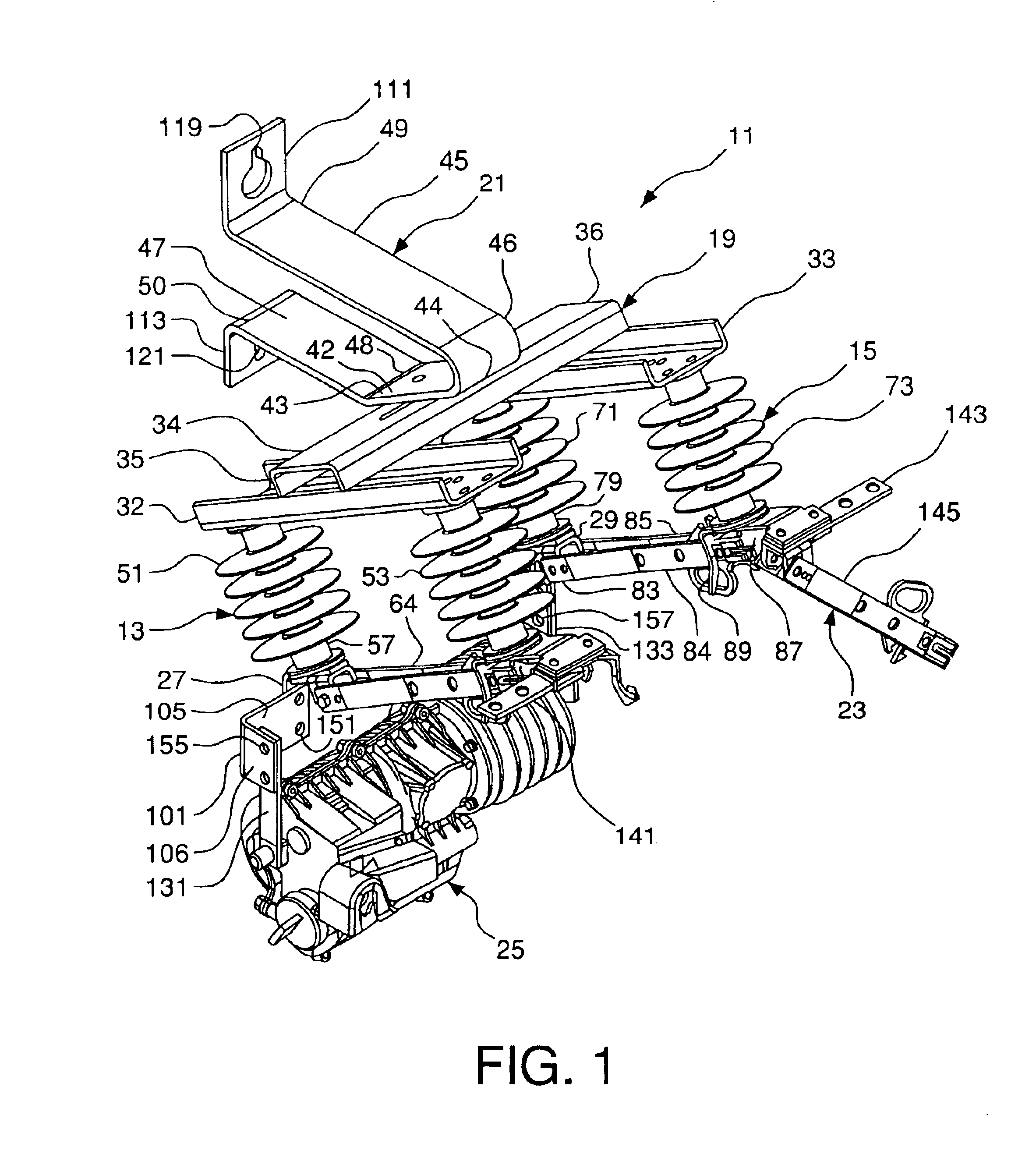
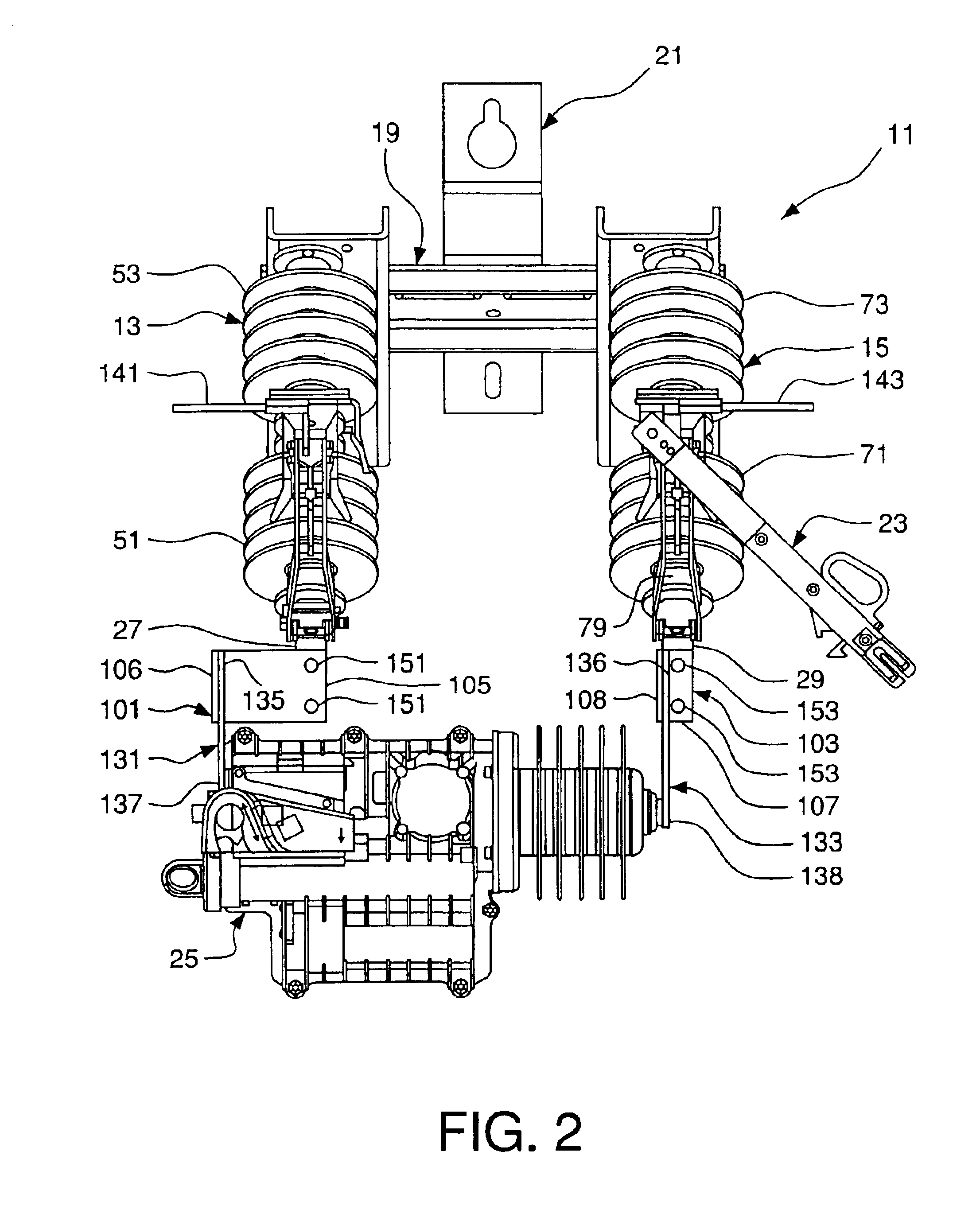
[0020]As shown in FIGS. 1-5, the present invention relates to a bypass recloser assembly 11. First and second switch assemblies 13 and 15 are mounted on a support assembly 19 secured to a support (not shown) by a mounting bracket 21. A bypass switch assembly 23 is electrically connected in parallel to the first and second switch assemblies 13 and 15, which are electrically connected in series. A recloser assembly 25 is secured to a first terminal pad 27 on the first switch assembly 13 and to a second terminal pad 29 on the second switch assembly 15 to provide both a mechanical and electrical connection. A recloser assembly that may be used is described in U.S. patent application Ser. No. 10 / 117,338 entitled Circuit Interrupting Device and filed on Apr. 8, 2002, now U.S. Pat. No. 6,753,493 which is hereby incorporated by reference in its entirety.

[0021]The first switch assembly 13, as shown in FIGS. 1-3, has first and second insulators 51 and 53. First insulator 51 has first and seco...


PUM


Abstract

A bypass switch recloser assembly has a first switch assembly connected electrically in series to a second switch assembly. A bypass switch assembly is connected electrically in parallel to the first and second switch assemblies. A recloser assembly is connected electrically in series to the first and second switch assemblies and electrically in parallel to the bypass switch assembly. The first, second and bypass switch assemblies and the recloser are mounted on a support assembly. The support assembly mounts the bypass switch recloser assembly to a support.

Description

FIELD OF THE INVENTION[0001]The present invention relates to a bypass recloser assembly. More particularly, the present invention relates to a bypass recloser assembly having a first switch assembly, a second switch assembly and a recloser assembly electrically connected in series, a bypass switch assembly connected electrically in parallel to the first and second switch assemblies and the recloser. The first, second and bypass switch assemblies and the recloser are connected to a support assembly for mounting the recloser assembly to a support.BACKGROUND OF THE INVENTION[0002]Distribution reclosers are mounted to support structures in electrical power distribution systems to prevent longer than momentary disruptions of electrical service, such as might be caused by a short circuit, and to provide continuous electric service. For example, wind conditions often cause power lines strung between poles to swing, thereby momentarily touching each other or a grounded conductor. Additional...

Claims


Application Information

Patent Timeline
Patent Type & Authority Patents(United States)
IPC IPC(8): H01H31/00H01H75/04H01H75/00
CPCH01H31/00H01H75/04H01H31/006H01H31/023H01H33/125
Inventor RHEIN, DAVID A.TAJ, HATIM H.THOMAS, JEFFERY L.
Owner HUBBELL INC
Learn More