
Hollow plastic bottle including vacuum panels

a vacuum panel and hollow plastic bottle technology, applied in the direction of rigid containers, large containers, packaging, etc., can solve the problems of side walls collapse inwardly, collapse under vacuum, and high stress points at the top and bottom edges of pressure panels

Inactive Publication Date: 2005-08-23
PLASTIPAK PACKAGING
View PDF15 Cites 70 Cited by
  • Summary
  • Abstract
  • Description
  • Claims
  • Application Information

AI Technical Summary

Benefits of technology

The present invention is a hollow plastic bottle with a unique design that allows for efficient and effective vacuum packaging. The bottle has a cylindrical body with a plurality of vacuum panels and elongated posts positioned between them, as well as top and bottom recessed bands. The bottom band is continuous around the entire circumference of the bottle, while the top band has at least two discontinuities with raised portions that interrupt the continuity of the band. This design ensures a tight seal and prevents leakage during storage and transportation.

Problems solved by technology

However, the inward flexing of the panels caused by the hot fill vacuum creates high stress points at the top and bottom edges of the pressure panels, and especially at the upper and lower corners of the panels.
These stress points weaken the portions of the side wall near the edges of the panels, allowing the side wall to collapse inwardly during handling of the container or when containers are stacked together.
However, despite these numerous designs it has been found that collapse under vacuum still occurs, especially in localized areas.

Method used


Image

  • Hollow plastic bottle including vacuum panels
  • Hollow plastic bottle including vacuum panels
  • Hollow plastic bottle including vacuum panels

Examples


Embodiment Construction

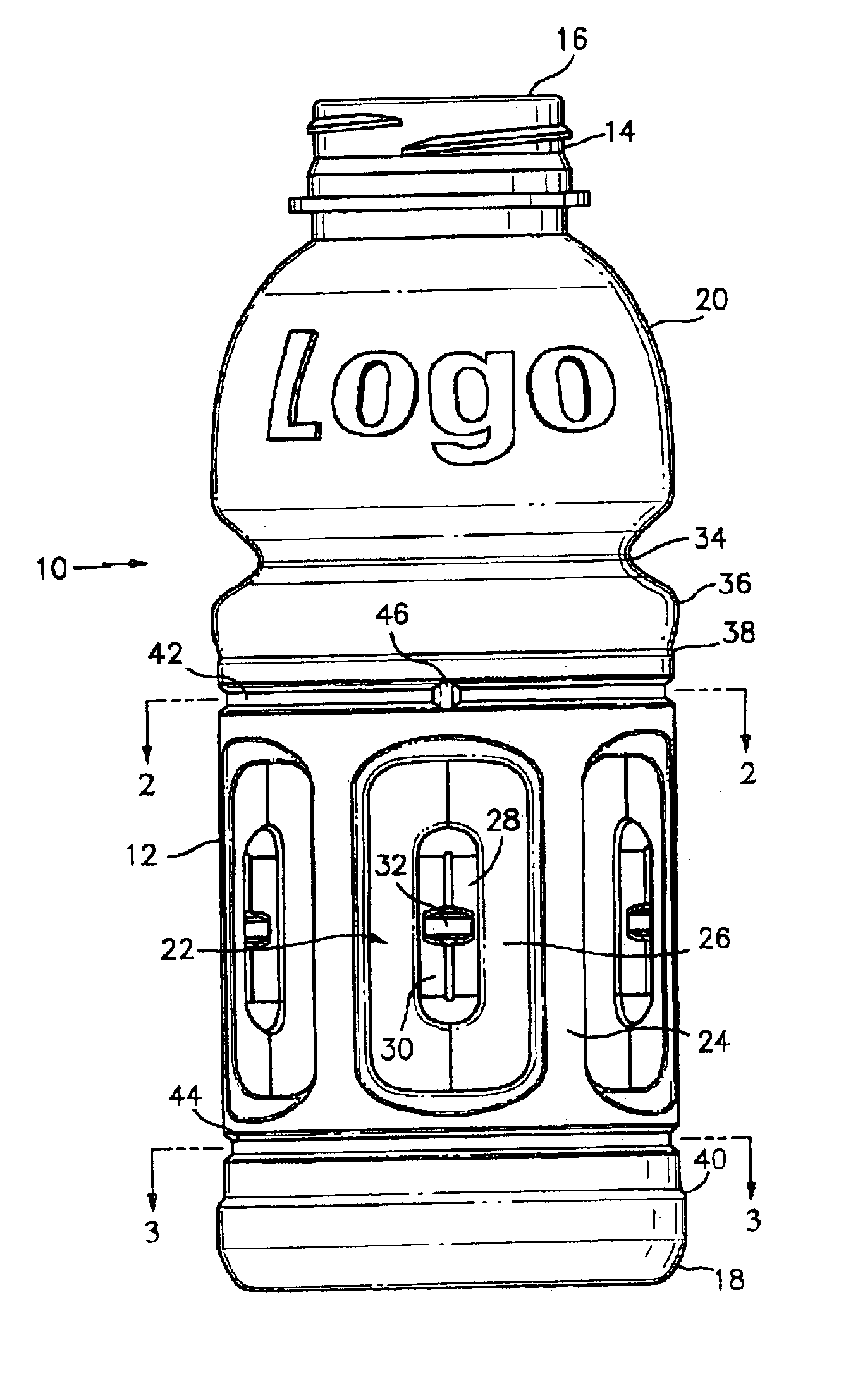
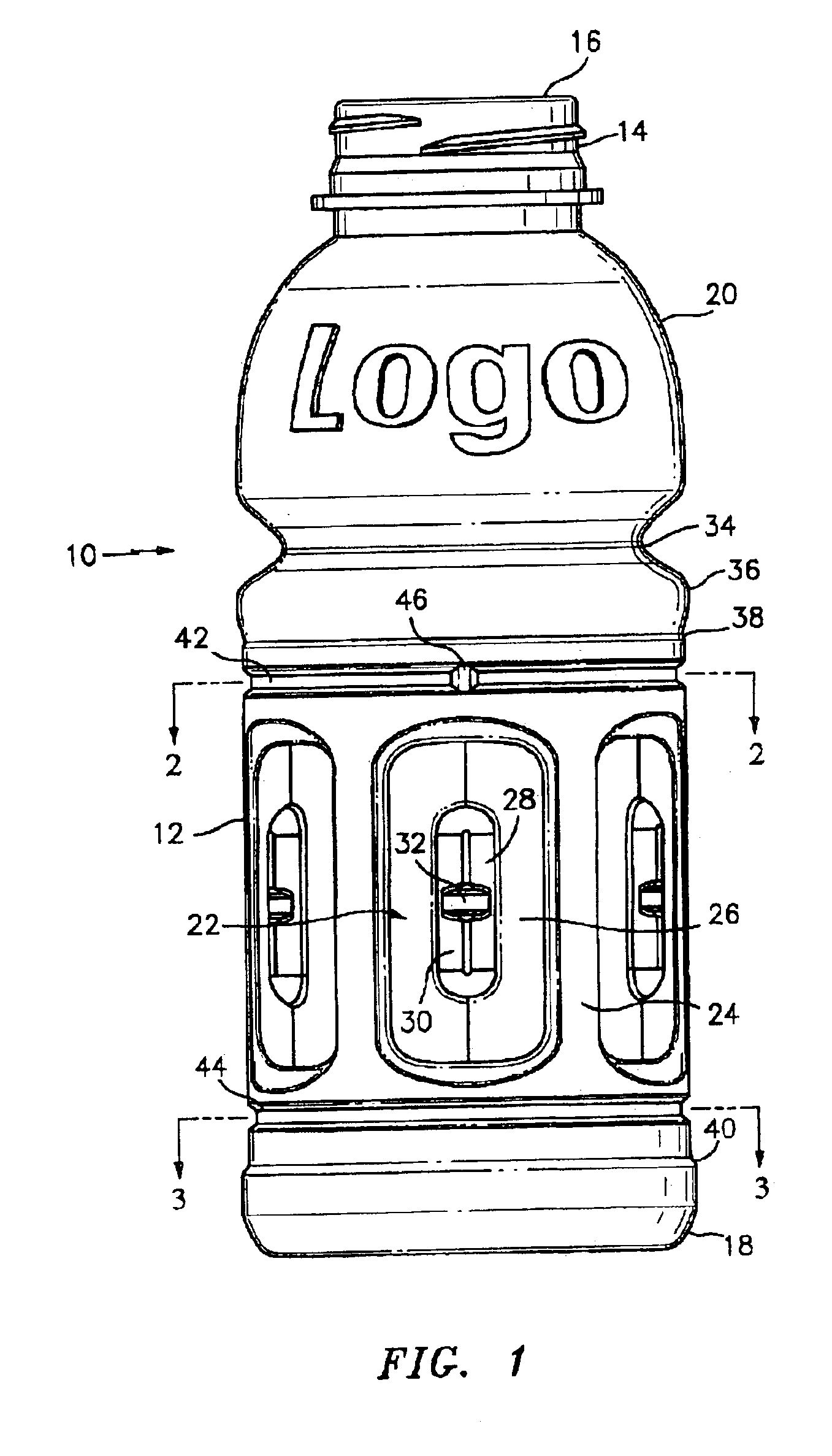
[0021]Referring to the drawings, the container 10 of the present invention shown in FIG. 1 includes a side wall portion 12, an upper end 14 with a dispensing opening 16 therein, which may be threaded as shown, suitable for receiving a closure (not shown), and a base portion 18. A generally dome shaped portion 20 is located between the side wall portion 12 and the upper end 14.

[0022]Container 10 is a hot-fill, blow molded plastic container which is particularly suited to be filled with a liquid at an elevated temperature and subsequently sealed. As the liquid cools its volume decreases in the sealed container. The container is produced from a thermoplastic material, as polyethylene terephthalate (PET), high density polyethylene (HDPE), polyethylene naphthalate, polyvinyl chloride, and others.

[0023]The side wall 12 includes a plurality of vertically elongated vacuum panels 22 which are disposed about the circumference of the container and are spaced apart from each other by smooth, ve...


PUM


Abstract

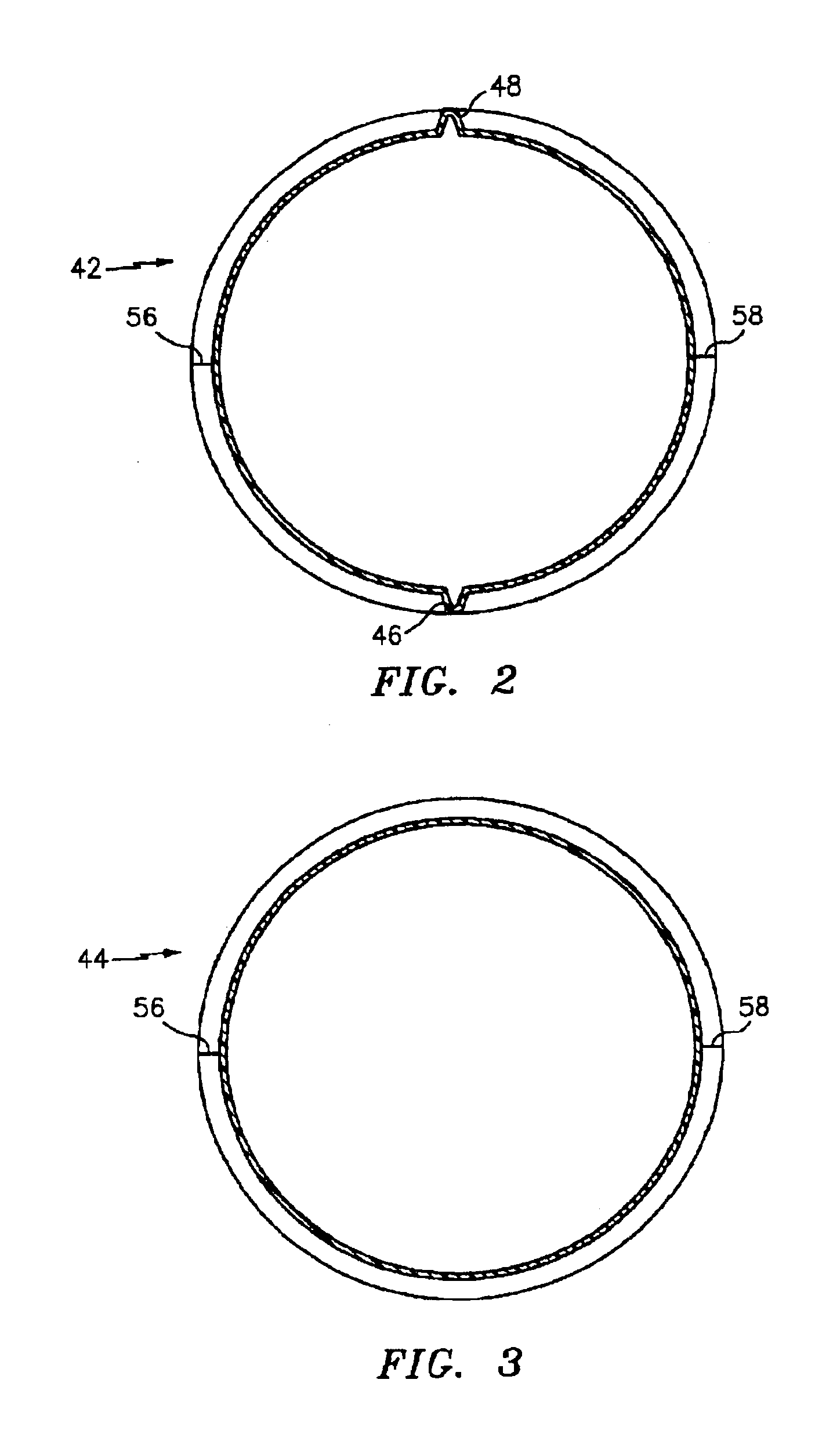
The hollow plastic bottle includes a side wall with a plurality of spaced apart vacuum panels and top and bottom recessed cylindrical bands above and below the vacuum panels. The bottom band extends continuously around the circumference of the bottle, and the top band includes at least two spaced apart discontinuities comprising raised portions interrupting the continuity of the top band.

Description

BACKGROUND OF THE INVENTION[0001]The present invention relates to an improved hot fillable plastic container having an improved side wall construction.[0002]The packaging of certain liquids requires that they be packaged while hot. During filling the container is subjected to elevated temperatures, the container is capped and as the product cools a negative internal pressure or hot fill vacuum is formed within the container. The container construction for a plastic container must be able to withstand such internal pressure changes while maintaining the container configuration.[0003]Various constructions have been proposed for plastic containers in an effort to maintain the integrity of the container during hot fill operations. Thus, the hot fill containers have been produced with a generally cylindrical main body which is provided with a plurality of elongated vertically oriented panels. These panels, which are commonly referred to as pressure or vacuum panels, are designed to colla...

Claims


Application Information

Patent Timeline
Patent Type & Authority Patents(United States)
IPC IPC(8): B65D79/00B65D1/02
CPCB65D1/0223B65D79/005B65D2501/0027B65D2501/0036B65D79/0084
Inventor PEDMO, MARC A.DARR, RICHARD C.
Owner PLASTIPAK PACKAGING
Learn More