Clutch

a technology of clutches and wing bodies, applied in the field of clutches, can solve the problems of electromagnetic clutches that cannot meet the requirements of reducing size and weight as well as cost, electromagnetic clutches are disadvantageous in their increased running cost, and the door is too heavy to manually open/close, so as to reduce the size and weight of the clutch, as well as the cost, and achieve the effect of power saving

Inactive Publication Date: 2005-08-23
NTN CORP
View PDF7 Cites 4 Cited by
  • Summary
  • Abstract
  • Description
  • Claims
  • Application Information

AI Technical Summary

Benefits of technology

[0008]The present invention has an object of applying a clutch previously proposed by the inventors of the present invention for a reclining seat of a vehicle or the like to the applications where an electromagnetic clutch is conventionally used so as to realize the reduction of the clutch in size and weight as well as in cost and the power saving.
[0010]In this clutch, the driven member is driven to rotate when the engaging element is moved to the engagement portion of the engaging element housing space by the operation means, whereas the driven member freely rotates when the engaging element is moved to the disengagement portion of the engaging element housing space. This clutch can be reduced in size and weight as well as in cost as compared with an electromagnetic clutch. Moreover, since the clutch is not required to be always electrically conducted, this clutch is also advantageous in terms of power saving.
[0012]In this case, a notch for allowing the elastic deformation of the retainer in the circumferential direction may be formed on one end of the retainer. With this structure, when the input rotational torque is to be transmitted or when the retainer is relatively moved in the axial direction, an internal stress generated in the retainer can be alleviated to prevent the retainer from being damaged.
[0013]Moreover, a clutch member engaged with any one of the input member and the driven member in the circumferential direction may be provided, and a cam face, with which the tapered roller is engaged in a wedgewise manner in the circumferential direction, may be provided for the clutch member. By thus providing the clutch member having an irregular-shaped cam face with which the tapered roller is engaged in a wedgewise manner as an independent member, the fabrication such as the formation of the cam face can be facilitated so as to reduce the cost.
[0014]Moreover, a guiding portion for guiding the retainer in the axial direction may be provided for the clutch member. With this structure, the retainer can be moved straight in the axial direction, thereby inhibiting the skew of the tapered roller and the like. As a result, an unexpected load can be prevented from being applied to the retainer.
[0016]In this case, the elastic energizing means can be constituted, on the larger side of the engaging element housing space, by a spring member inserted between an inwardly-oriented or outwardly-operated flange provided for any one of the input member and the driven member and one end of the retainer. As the spring member, for example, a waved spring having a waved cross section is inserted so as to obtain the ensured pressing energizing function. In addition, the size can be compact with the use of the waved spring.

Problems solved by technology

In the case where the sliding door is to be manually opened / closed when a power switch is OFF or during a blackout, the door is too heavy to manually open / close because a rotor of the motor rotates along with the door movement.
Therefore, in many cases, the electromagnetic clutch cannot meet the requirements of reduction in size and weight as well as in cost.
Moreover, since the electromagnetic clutch is required to be always electrically conducted so as to maintain a torque transmission state, the electromagnetic clutch is disadvantage in its increased running cost.

Method used


Image

  • Clutch
  • Clutch
  • Clutch

Examples


Embodiment Construction

[0032]Hereinafter, a clutch according to one embodiment of the present invention will be described with reference to the accompanying drawings.

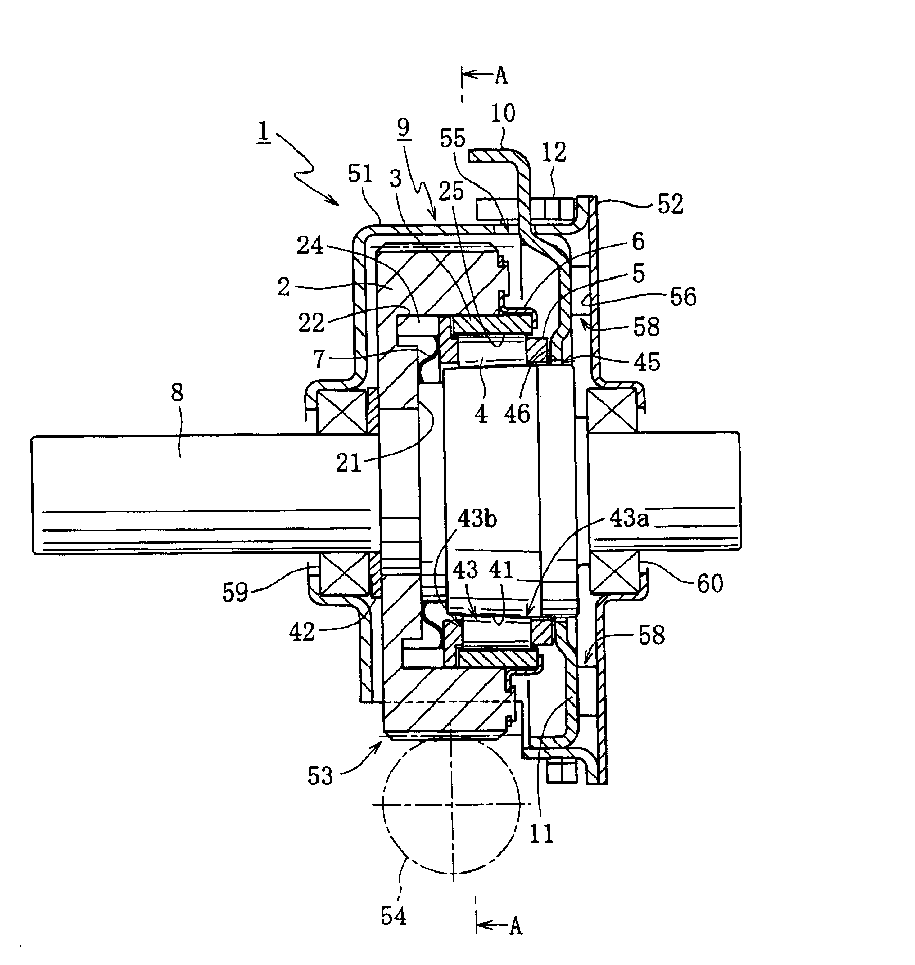
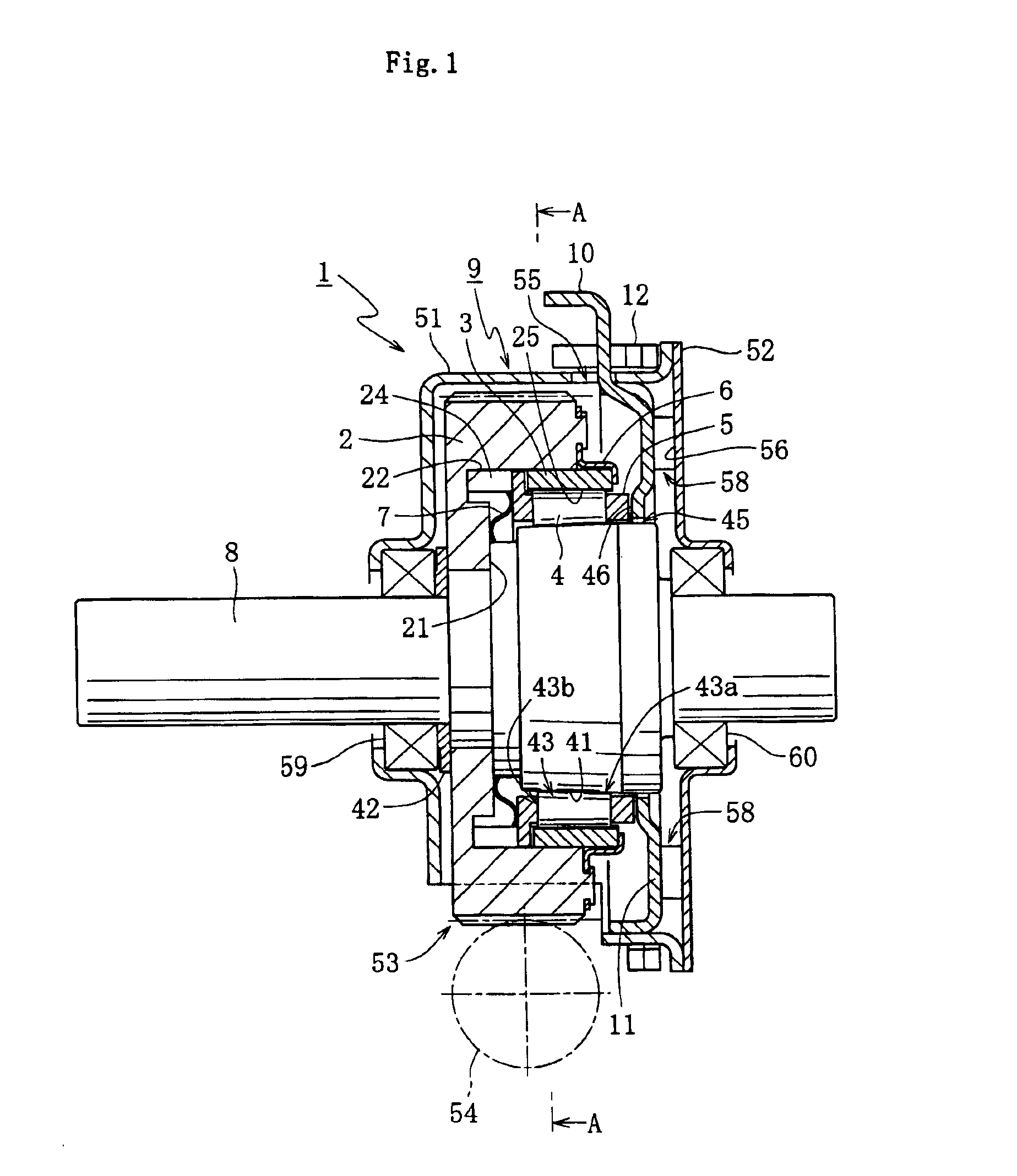
[0033]As shown in FIG. 1, a clutch 1 includes: an input gear 2 to which a rotational torque is input; a clutch member 3 attached to an inner circumferential face of the input gear 2; a tapered roller 4 acting as an engaging element; a retainer 5 for holding the tapered roller 4; a cap member 6; a waved spring 7; an output shaft 8 serving as a driven member; a housing 9 for sheathing the input gear 2; a working member 11 equipped with an operating lever 10; and a return spring 12 serving as an elastic return member, for elastically supporting the working member 11. FIG. 1 shows a state where the output shaft 8 is driven by the input gear 2 to cause its rotation.

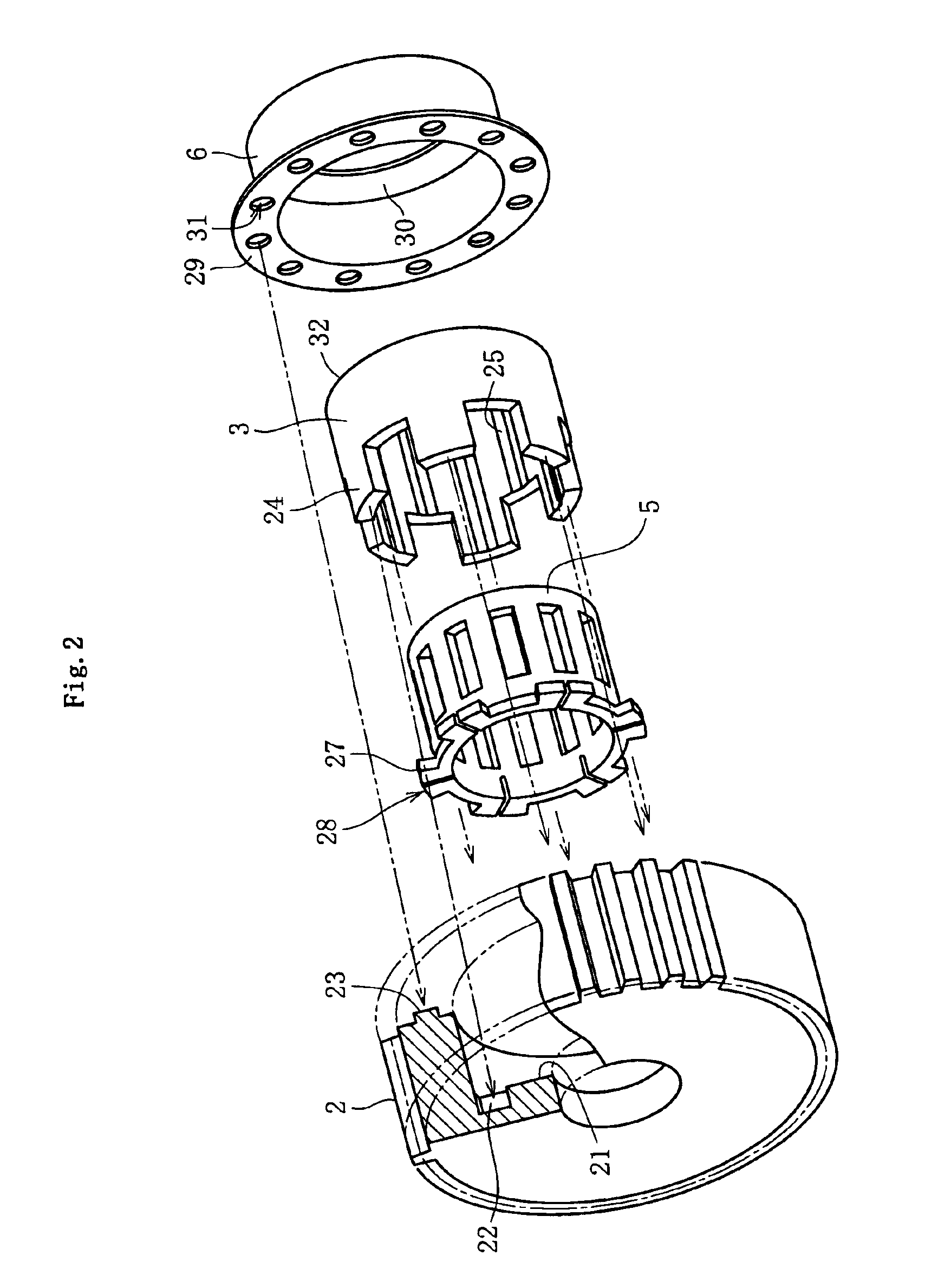
[0034]As shown in FIG. 2, the input gear 2 has teeth on its outer circumferential face. The input gear 2 has an inwardly-oriented flange portion 21 on one side in the axial direction (o...


PUM


Abstract

A clutch, which is applicable to the applications where an electromagnetic clutch is conventionally used, is provided in order to realize the reduction of the clutch in size, weight and cost and the power saving of the clutch. A clutch according to the present invention includes: an input gear to which a rotational torque is input; a clutch member attached to an inner circumferential face of the input gear; a tapered roller acting as an engaging element; a retainer for holding the tapered roller; a cap member; a waved spring; an output shaft serving as a driven member; a housing for sheathing the input gear; a working member equipped with an operating lever; and a return spring serving as an elastic return member, for elastically supporting the working member. With a simple operation of pivoting the operating lever of the working member, the clutch can be easily switched between a state where the tapered roller is engaged in a wedgewise manner so as to drive and rotate the output shaft and a state where the wedge engagement of the tapered roller is cancelled to freely rotate the output shaft.

Description

BACKGROUND OF THE INVENTION[0001]1. Field of the Invention[0002]The present invention relates to a clutch including an engaging element enabling the wedge engagement in the circumferential direction between an input member to which a rotational torque is input and a driven member. An operation state of the clutch is switchable between a state where the rotational torque is transmitted from the input member to the driven member and a state where the driven member freely rotates with respect to the input member. Such a clutch is applicable to, for example, a mechanism for switching an electrically-operated sliding door between an automatic opening / closing state and a manual opening / closing state.[0003]2. Description of the Related Art[0004]Conventionally, in an electrically-operated sliding door, the input of a rotational torque from a motor (driving device) drives a driving mechanism for a door in a forward / reverse rotation direction to open / close the door. In the case where the slid...

Claims


Application Information

Patent Timeline
Patent Type & Authority Patents(United States)
IPC IPC(8): E05F15/10F16D41/00F16D41/08E05F15/16F16D13/32F16D15/00
CPCE05F15/603F16D41/086E05Y2900/55E05F15/692
Inventor KURITA, MASAHIRO
Owner NTN CORP
Why Eureka
Try Eureka