
Method for correcting position error in navigation system

a navigation system and position error technology, applied in the field of navigation systems, can solve problems such as the error range of sensors such as a gyro (or gyroscope) or electronic compass built in the moving object, and the serious damage to the safety of the operator of the moving object,

Inactive Publication Date: 2005-08-16
LG ELECTRONICS INC
View PDF8 Cites 62 Cited by
  • Summary
  • Abstract
  • Description
  • Claims
  • Application Information

AI Technical Summary

Benefits of technology

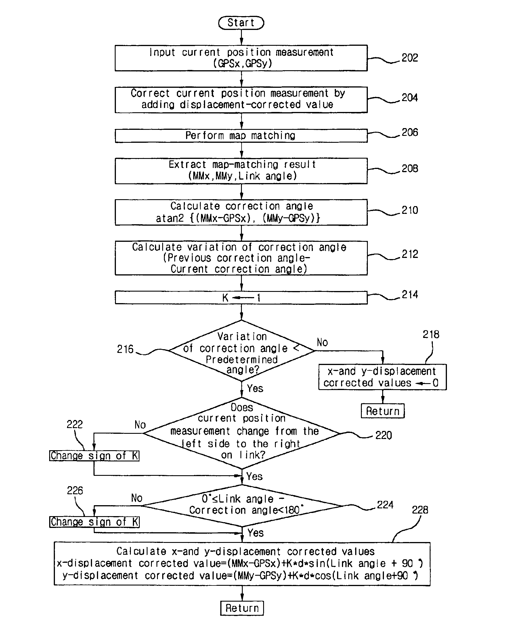
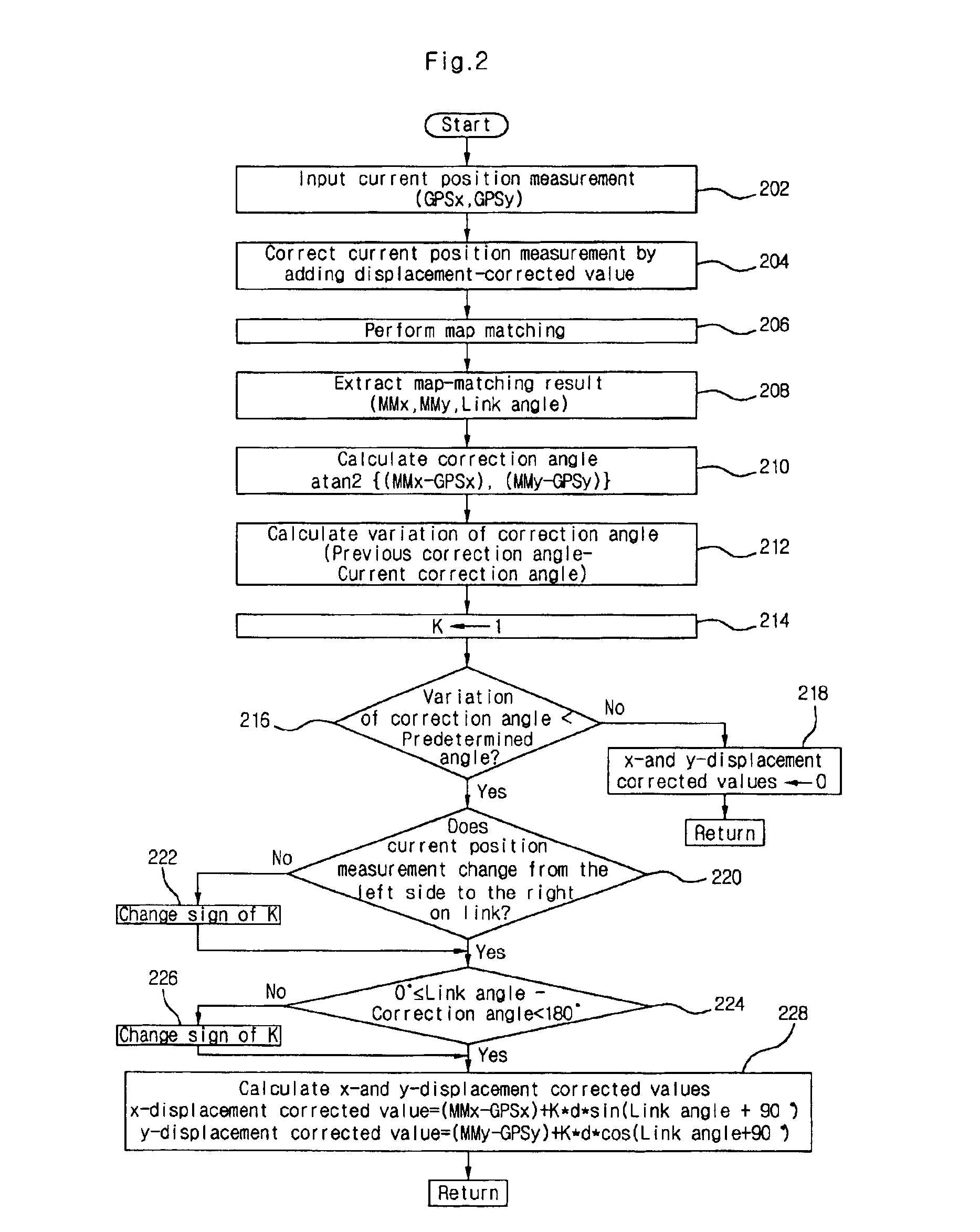
[0014]Accordingly, one object of the present invention is to solve the foregoing problems by providing a method for correcting position error in a navigation system, enabling to match a measurement position of a moving object with a digital map.
[0015]Another object of the present invention to provide a method for correcting position error in a navigation system, capable of accurate matching of a current position of a moving object with a link on a digital map by measuring the current position of the moving object, adding to a measurement a displacement-corrected value obtained from a previous map matching so as to correct the measurement, and performing map matching.
[0017]Still another object of the present invention is to provide a method for correcting position error in a navigation system, in which measurement position of a moving object is used to find a node between interpolation points of a candidate link having a highest possibility to be matched on a map.

Problems solved by technology

Providing incorrect current positions of the moving object or providing position information discontinuously may cause serious damages on the safety of an operator of the moving object, so the determination of current positions of the moving object is very important.
Navigation systems do not always provide accurate information on a current position of the moving object.
That is, the error range of sensors such as a gyro (or gyroscope) or electronic compass built in the moving object could be great, depending on rotation direction of the moving object.
Also, when the moving object stops, its heading may be deflected in one direction or be changed, making position errors on heading of the moving object.
Moreover, measurement of traveling distance of the moving object using a wheel sensor can be erroneous also because the wheel sensor is very sensitive to external factors like air pressure of wheels / tires and road surface conditions.
Many times, however, operators of moving objects do not drive along an intersection or central line on a road, and as a result, the digital map itself have errors thereon.
In addition, errors are also made when inputting data in the digital map, marking the position of the moving object at an incorrect spot.
However, the above technique did not really use the result of map matching to trace the moving object.
Therefore, it was rather difficult to do perfect matching of the position of the moving object with the digital map.
The position of the moving object on a straight road can be easily matched with the digital map, but on a curved road, accurate positioning is very difficult.

Method used


Image

  • Method for correcting position error in navigation system
  • Method for correcting position error in navigation system
  • Method for correcting position error in navigation system

Examples


Embodiment Construction

[0028]The following detailed description will present a method for correcting position error in a navigation system according to a preferred embodiment of the invention in reference to the accompanying drawings.

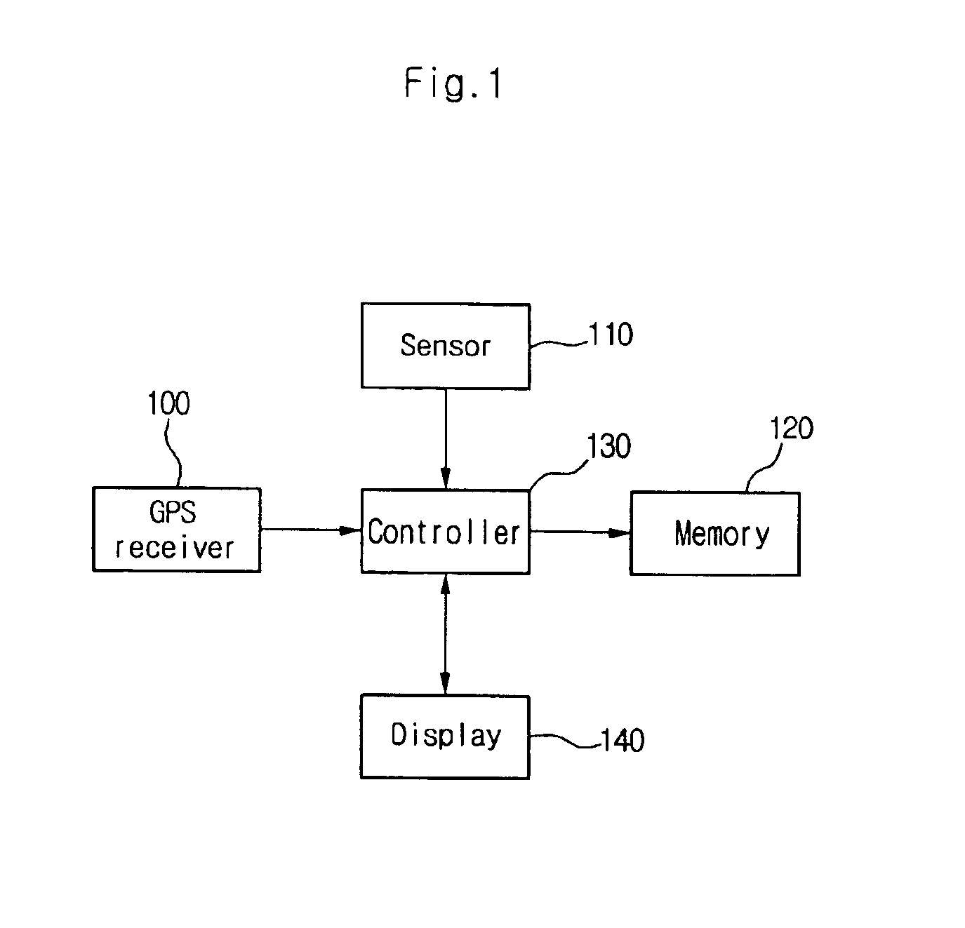
[0029]FIG. 1 is a block diagram of the configuration of a navigation system according to one embodiment of the present invention.

[0030]As shown in FIG. 1, the navigation system includes a GPS receiver 100 for detecting current position information of a moving object by using a signal transmitted from a plurality of satellite GPSs, a sensor 110 for detecting driving speed and rotational direction of the moving object by making use of a gyro and speed sensor installed in the moving objection, a memory 120 for storing digital map information, information on the moving object's driving path and an operational program, a controller 130 for deciding a current position of the moving object by correcting the moving object's current position measured using output signals from the GPS ...


PUM


Abstract

A method for correcting position error in a navigation system enables one to more accurately match a position measurement of a moving object on a digital map. Particularly, the method comprises the steps of: receiving a current position measurement of a moving object from GPS / DR (Dead Reckoning)-based information; correcting the current location measurement using a displacement-corrected value; performing map matching using the corrected current position measurement; calculating variation of correction angle by extracting a current correction angle out of the map matching result; converting and correcting a previous displacement-corrected value to the current correction angle; and compensating the displacement-corrected value by applying a predetermined constant to the converted displacement-corrected value, and storing the compensated displacement-corrected value.

Description

[0001]This nonprovisional application claims priority under 35 U.S.C. §119(a) on Patent Application No. 10-2002-0052413 filed in KOREA on Sep. 2, 2002, which is herein incorporated by reference.BACKGROUND OF THE INVENTION[0002]1. Field of the Invention[0003]The present invention relates in general to a navigation system, more particularly, to a method for correcting position error in a navigation system which utilizes a map matching (MM) in order to provide an accurate information on a current position of a moving object by correcting position errors in consideration of position measurements of a mobile object including vehicles, airplanes and ships, and the shape of a road (i.e. link) displayed on a digital map.[0004]2. Discussion of the Background Art[0005]An essential element of navigation systems is the determination of a current position of a moving object (e.g. vehicles) within an allowable range of error, and providing such information to a driver of the moving object continu...

Claims


Application Information

Patent Timeline
IPC IPC(8): G01C21/30G01C21/28G01S5/14G01C21/00G01S19/14G08G1/0968
CPCG01C21/30G01S19/49G01S19/50G08G1/0968
Inventor JUNG, MUN HOJOE, MOON JEUNG
Owner LG ELECTRONICS INC
Learn More