
GPS-based control system and method for controlling mechanized irrigation systems

a technology of mechanized irrigation and control system, which is applied in the direction of process and machine control, watering devices, instruments, etc., can solve the problems of difficult to stop, reverse and/or change the speed of the system accurately, and the encoder does not provide positive feedback of the movement of the end tower, etc., to achieve high degree of accuracy and consistency

Inactive Publication Date: 2005-08-09
REINKE MFG
View PDF38 Cites 60 Cited by
  • Summary
  • Abstract
  • Description
  • Claims
  • Application Information

AI Technical Summary

Benefits of technology

"The present invention provides an improved GPS-based control system for controlling various functions of a sprinkler irrigation system with a high degree of accuracy and consistency. The control system can be used with either a center pivot irrigation system or a linear move irrigation system and requires only one GPS receiver to determine the position of the sprinkler system. The control system is reliable, economical, and easy to set up. It provides a high degree of accuracy for controlling the end gun operation of a center pivot sprinkler irrigation system. The control system is also efficient in use, long operating life, and well-suited for use in both pivot and linear move sprinkler irrigation systems."

Problems solved by technology

The encoder does not provide positive feedback of when the end tower is moving.
As a result, the end gun is not always activated at the most advantageous position of the end tower, and it is difficult to stop, reverse and / or change the speed of the system accurately because the exact location of the end tower is not known.
Until recently the use of Global Positioning Satellite (GPS) data to locate the end tower of a center pivot irrigation system would have been impractical from the standpoint that such position calculations were too inaccurate and GPS receiver / senders were prohibitively expensive.

Method used


Image

  • GPS-based control system and method for controlling mechanized irrigation systems
  • GPS-based control system and method for controlling mechanized irrigation systems
  • GPS-based control system and method for controlling mechanized irrigation systems

Examples


Embodiment Construction

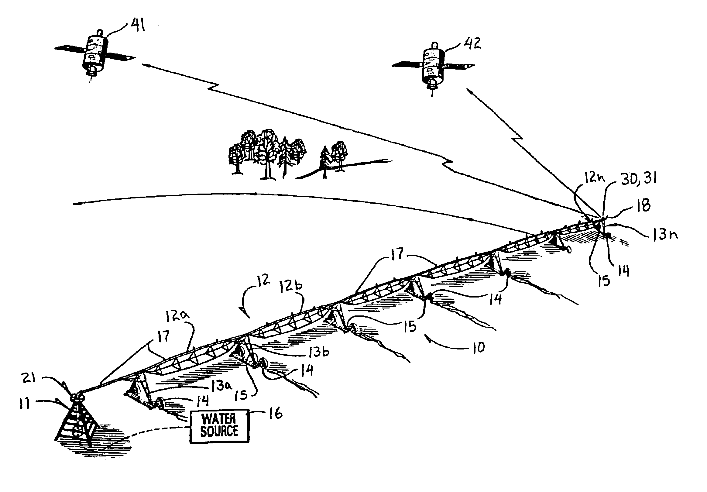
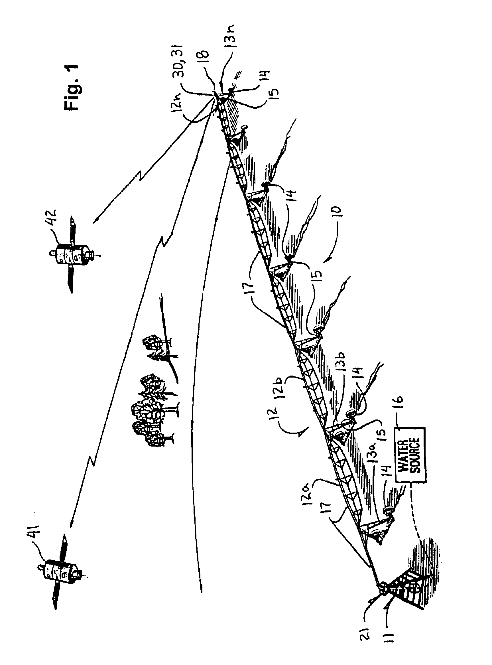
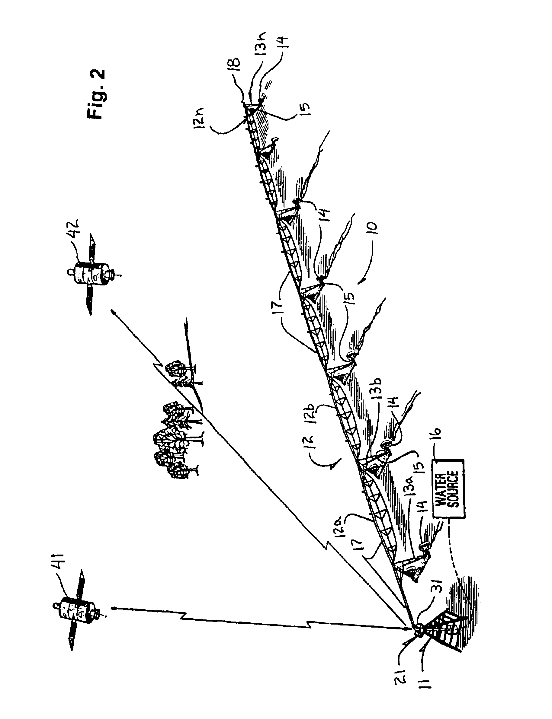
[0027]A GPS-based controller for irrigation systems according to the present invention will now be described with reference to FIGS. 1 to 5 of the accompanying drawings.

[0028]The GPS-based controller of the present invention will first be described in conjunction with a center pivot sprinkler irrigation system 10. A center pivot 11 for the irrigation system 10 is stationary and connected to a main boom 12, which can be comprised of several separate boom sections 12a, 12b . . . 12n. The boom sections 12a-12n are supported by support towers 13a-13n, each of which have wheels 14 and drive motors 15 for mobility.

[0029]The center pivot 11 is connected to a source of water, such as a well 16. Water is supplied from the well 16 along the lengths of the main boom 12 for delivering a desired amount of water to a plurality of sprinkler heads 17, which are spaced along the lengths of the boom sections 12a-12n. Water is also delivered through the main boom 12 to an end gun assembly 18 positione...


PUM


Abstract

A GPS-based control system for irrigation systems includes a power supply, a nonvolatile memory for storing a first set of coordinates corresponding to a reference position for the irrigation system, circuitry for receiving GPS data and using the data to generate a second set of coordinates corresponding to a current position of the irrigation system, and a microprocessor for calculating the azimuth and the distance between the reference position and the current position using the first and second sets of coordinates. The control system communicates with a main controller of the irrigation system to control a function of the irrigation system, such as stopping, reversing, end gun operation, application rate, or other auxiliary output, at a selected distance or azimuth value of the current position relative to the reference position. The control system can be used with either a center pivot irrigation system or a linear move irrigation system.

Description

BACKGROUND OF THE INVENTION[0001]1. Field of the Invention[0002]The present invention relates generally to mechanized irrigation systems. In particular, the present invention relates to a GPS-based control system for determining the angular position of a center pivot irrigation system, or for determining the distance traveled by a linear move irrigation system, and using the information to control a function of the irrigation system.[0003]2. Description of the Related Art[0004]Mechanized sprinkler irrigation systems are widely used throughout the world to provide water for agricultural purposes in arid regions. Typically, such systems include a series of spaced support towers connected by truss sections that support an elevated water distribution pipe between the towers. In center pivot systems, the water distribution pipe extends radially from a central pivot communicating with a pressurized water supply. In linear move irrigation systems, the water distribution pipe extends latera...

Claims


Application Information

Patent Timeline
Patent Type & Authority Patents(United States)
IPC IPC(8): A01G25/16A01G25/09A01G25/00
CPCA01G25/092A01G25/16Y02A40/22
Inventor BARKER, LUKE J.
Owner REINKE MFG
Learn More