
Heart rate transmitter

Inactive Publication Date: 2005-08-09
CHEN TONG PIE
View PDF6 Cites 28 Cited by
  • Summary
  • Abstract
  • Description
  • Claims
  • Application Information

AI Technical Summary

Benefits of technology

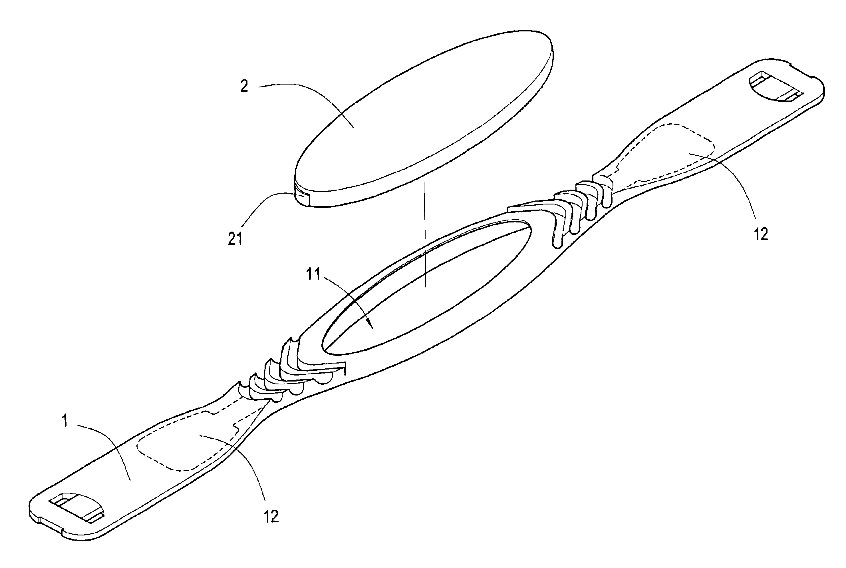
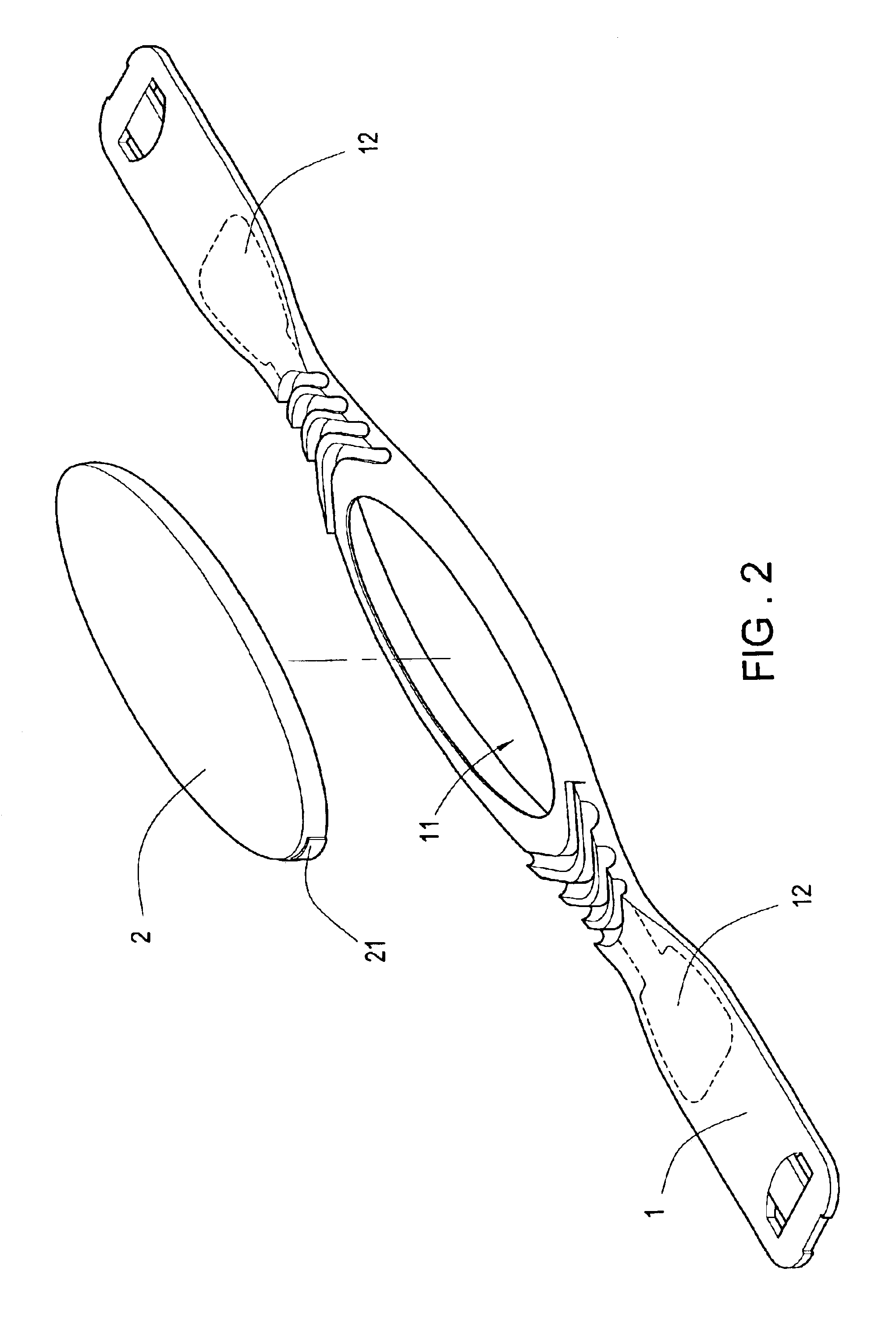
[0007]It is therefore a primary object of the invention to provide a heart rate transmitter comprising a strap and a body. Users can press the body into the strap, the two contacting points on both ends of the body can contact firmly onto the contacting tip on the end of the conducting rubber plate of the strap, such scheme can avoid the inconvenience and troublesome of application of tools to assemble.

Problems solved by technology

Such procedure is not very convenient and has to apply many screws to fix all the components together; the manufacturing cost is higher to reduce the market competition.

Method used


Image

  • Heart rate transmitter
  • Heart rate transmitter
  • Heart rate transmitter

Examples


Embodiment Construction

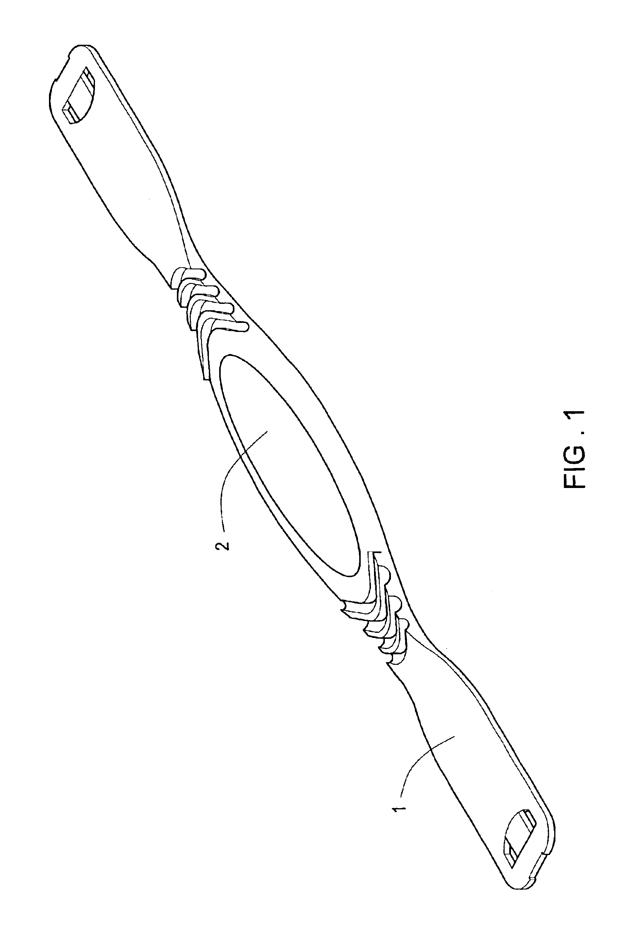
[0017]Referring to FIG. 1, FIG. 2 and FIG. 3, the present invention is composed of a strap (1) and a body (2). The functions of each component are described below:

[0018]The strap (1) is in long belt shape, a hole (11) is in the center of the strap (1), a conducting rubber plate (12) each is on both ends of the hole (11) of the strap (1), as shown in FIG. 4, a contacting tip (12a) stretches out from the conducting rubber plate (12) to the inner side of the hole (11).

[0019]The body (2) is installed inside the hole (11) of the strap (1), two contacting point (21) are on both ends of the body (2); when the body (2) is inserted into the hole (11) of the strap (1), two contacting point (21) are pressed to contact the contacting tip (12a) of the conducting rubber plate (12) inside the hole (11) of the strap (1), as shown in FIG. 3; the contacting point (21) of the body (2) can contact the conducting rubber plate (12), as shown in FIG. 5, the conducting rubber plate (12) contacts human body...


PUM


Abstract

A heart rate transmitter comprising a strap and a body. The strap is in long belt shape, a hole is in the center of the strap, a conducting rubber plate each is on both ends of the hole, a contacting tip stretches out from the conducting rubber plate to the inner side of the hole. The body is installed inside the hole of the strap; two contacting points are on both ends of the body. When the body is inserted into the hole of the strap, two contacting points are pressed to contact the contacting tips of the conducting rubber plate inside the hole of the strap; the conducting rubber plate contacts human body to measure the heartbeat rate.

Description

BACKGROUND OF THE INVENTION[0001]I. Field of the Invention[0002]This invention relates generally to a heart rate transmitter and, more specifically, to a heart rate transmitter that users can put the transmitter body into the strap, the two contacting points on both ends of the body can contact firmly onto the contacting tip on the end of the conducting rubber plate of the strap, such scheme can avoid the inconvenience and troublesome of application of tools to assemble.[0003]II. Description of the Prior Art[0004]Heretofore, it is known that a prior heart rate transmitter, as shown in FIG. 6, is composed of a base shell (a) with two conducting plate (b) on top of both ends, a circuit board (c) is installed on top of the base shell (a); two conducting spring (c1) are on the bottom of the circuit board (c) to press on the conducting plate (b); a left strap (d1) and a right strap (d2) are on both ends of the base shell (a), a conducting rubber plate (e) each is fixed on the left strap ...

Claims


Application Information

Patent Timeline
IPC IPC(8): A61B5/0408
CPCA61B5/0408A61B5/6831A61B5/25
Inventor CHEN, TONG-PIE
Owner CHEN TONG PIE
Learn More