
Surgical blade for use with a surgical tool for making incisions for scleral eye implants

a surgical tool and incision making technology, applied in the field of scleral eye implants, can solve the problems of not being able to restore the accommodative power of presbyopia, difficult to make precise incisions, and other physicians who do not practice surgery regularly are less skilled, so as to achieve the effect of restricting movemen

Inactive Publication Date: 2005-08-09
REFOCUS GROUP
View PDF20 Cites 53 Cited by
  • Summary
  • Abstract
  • Description
  • Claims
  • Application Information

AI Technical Summary

Benefits of technology

[0029]It is also another object of the present invention to provide an improved blade guide for guiding the motion of a surgical blade in the surgical tool of the present invention.
[0030]It is a further object of the present invention to provide a scleral tissue fixation tool that is capable of restraining the movement of the sclera of the eye away from the surgical blade of the surgical tool of the present invention when an incision is being made in the sclera of the eye.
[0031]It is another object of the present invention to provide a vacuum operated blade guide that is capable of restraining the movement of the sclera of the eye away from the surgical blade of the surgical tool of the present invention by applying a vacuum to the surface of the sclera of the eye.

Problems solved by technology

According to the conventional view, it is not possible by any treatment to restore the accommodative power to the presbyopic eye.
Other physicians who do not practice surgery regularly are less skilled.
Even skilled surgeons may find it difficult to make the precise incisions that are required to correctly form a scleral pocket.
If scleral pocket incisions are not made with sufficient precision the resulting scleral pocket will not be able to correctly support a scleral prosthesis.
An incorrectly supported scleral prosthesis is not able to provide an acceptable level of vision correction.

Method used


Image

  • Surgical blade for use with a surgical tool for making incisions for scleral eye implants
  • Surgical blade for use with a surgical tool for making incisions for scleral eye implants
  • Surgical blade for use with a surgical tool for making incisions for scleral eye implants

Examples


Embodiment Construction

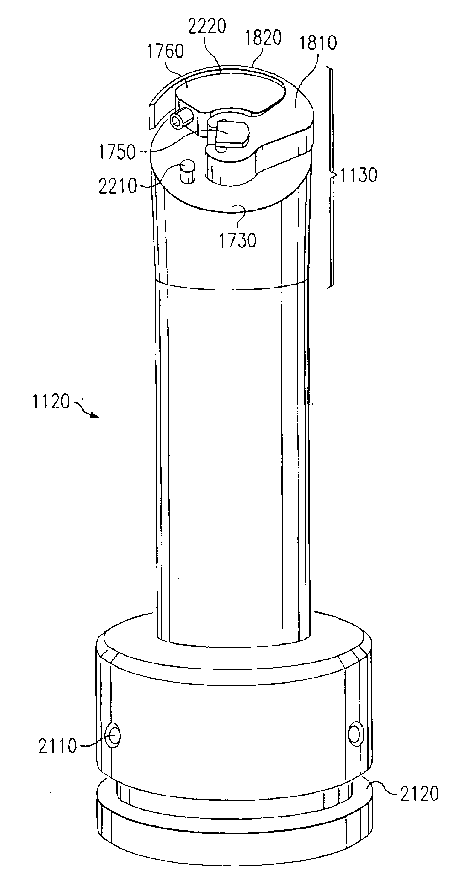
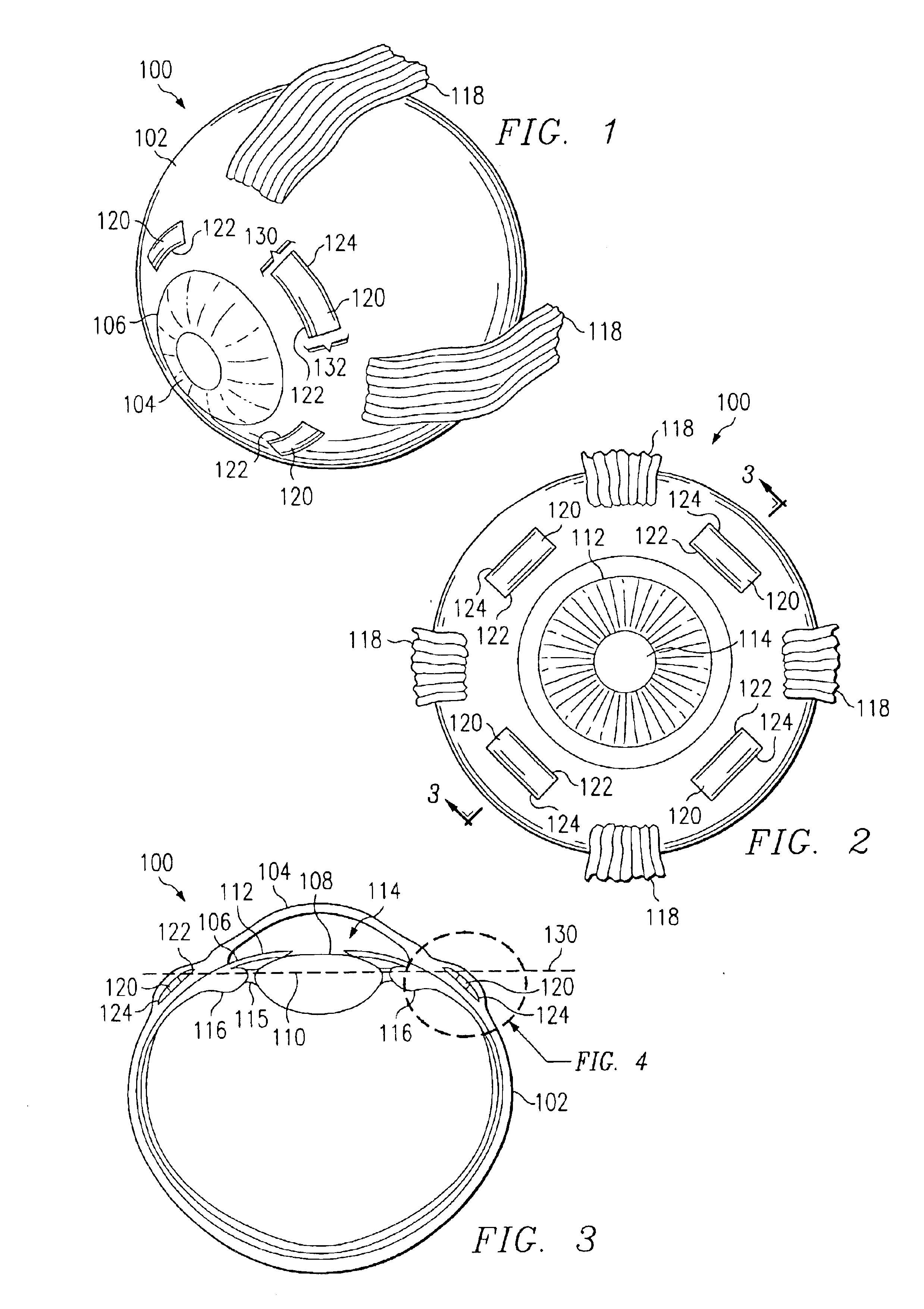
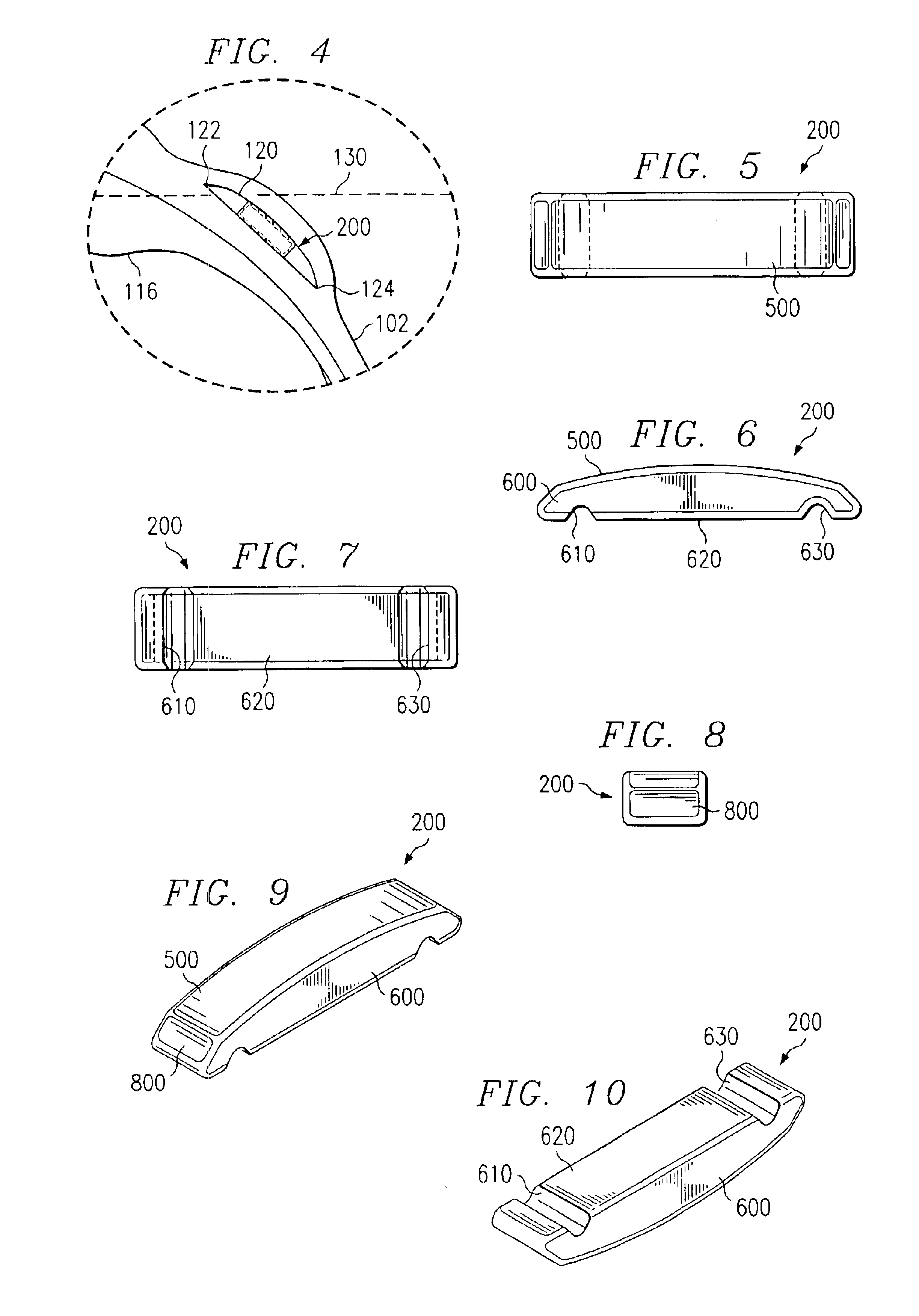
[0084]FIGS. 1 through 48, discussed below, and the various embodiments used to describe the principles of the present invention in this patent document are by way of illustration only and should not be construed in any way to limit the scope of the invention. Those skilled in the art will understand that the principles of the present invention may be implemented in any suitably arranged surgical tool and with any suitable surgical method.

[0085]The system and method of the present invention comprise a surgical tool that is capable of making incisions in the sclera of an eye in order for the eye to receive a scleral prosthesis. Scleral prostheses are used to treat presbyopia (and other similar eye disorders) by increasing the effective working distance of the ciliary muscle of the eye. This is accomplished by increasing the distance between the ciliary muscle and the lens equator by increasing the diameter of the sclera in the region of the ciliary body.

[0086]The effective working dis...


PUM


Abstract

A surgical blade is disclosed for use with a surgical tool for making incisions in the sclera of an eye to form a scleral pocket to receive a scleral prosthesis. The surgical blade comprises a rotatable support arm capable of being rotated by the surgical tool and a detachable curved cutting blade for making incisions in the sclera of an eye. The surgical tool causes the curved cutting blade to advance through the sclera to form an incision having dimensions to receive a scleral prosthesis. When the incision is complete the curved cutting blade is detached from the rotatable support arm. The curved cutting blade is then removed from the incision by pulling the curved cutting blade forward out of the incision. The incision has the exact dimensions to receive a scleral prosthesis.

Description

PRIORITY CLAIM TO PROVISIONAL PATENT APPLICATION[0001]This patent application claims priority to U.S. Provisional Patent Application Ser. No. 60 / 271,028 filed on Feb. 23, 2001.CROSS-REFERENCE TO RELATED PATENT DOCUMENTS[0002]The present disclosure is related to the inventions disclosed in the following United States patent applications and issued United States patents:[0003](1) U.S. Pat. No. 6,299,640 entitled “SCLERAL PROSTHESIS FOR TREATMENT OF PRESBYOPIA AND OTHER EYE DISORDERS” issued on Oct. 9, 2001;[0004](2) U.S. Pat. No. 6,197,056 entitled “SEGMENTED SCLERAL BAND FOR TREATMENT OF PRESBYOPIA AND OTHER EYE DISORDERS” issued on Mar. 6, 2001;[0005](3) U.S. Pat. No. 6,280,468 entitled “SCLERAL PROSTHESIS FOR TREATMENT OF PRESBYOPIA AND OTHER EYE DISORDERS” issued Aug. 28, 2001;[0006](4) U.S. Pat. No. 5,465,737 entitled “TREATMENT OF PRESBYOPIA AND OTHER EYE DISORDERS” issued on Nov. 14, 1995;[0007](5) U.S. Pat. No. 5,489,299 entitled “TREATMENT OF PRESBYOPIA AND OTHER EYE DISORDER...

Claims


Application Information

Patent Timeline
IPC IPC(8): A61F2/14A61F9/007A61F9/013
CPCA61F2/147A61F9/013A61F9/0133
Inventor SCHACHAR, RONALD A.CUDMORE, DONALD P.
Owner REFOCUS GROUP
Learn More