Eureka AIR delivers breakthrough ideas for toughest innovation challenges, trusted by R&D personnel around the world.

Integrated light-guide and dome-sheet for keyboard illumination

a dome-sheet and light-guide technology, applied in the field of illumination systems, can solve the problems of small fraction of the power provided electrically to the led actually being transferred, the difficulty of efficiently guiding the optical power to the illuminated area, and the significant drain on the power source available to the electronic devi

Inactive Publication Date: 2005-08-09
NOKIA TECHNOLOGLES OY
View PDF10 Cites 82 Cited by
  • Summary
  • Abstract
  • Description
  • Claims
  • Application Information

AI Technical Summary

Benefits of technology

[0017]Preferably, each of the touch members has a dome shape protruding above the upper boundary interface of the sheet, and a light escapement surface is disposed at each touch area. The light escapement surface can be provided on the upper surface or the lower surface of the dome. Preferably, each of the touch members has one or more electrically conducting areas disposed in the lower surface. The electronically conducting areas are capable of interacting with the electronic circuit for activating the keys when the user touches the touch members.

Problems solved by technology

The use of multiple LEDs for illumination causes a significant drain on the power source available to the electronic device.
In particular, when a lambertian emitting LED is used to illuminate an area of the user interface, only a small fraction of the power provided electrically to the LED actually transfers to the optical power reaching that area.
Moreover, guiding this optical power efficiently to the illuminated area is very difficult.
As a result, the waste in the electrical power provided to the LEDs is significant.
In an electronic device having many separate illuminated areas, the thickness of the light guide will become very uneven in that some sections of the light guide may be too thick, while the other sections may be too thin.
Disposing such a light guide in a small hand-held device may be difficult.

Method used


Image

  • Integrated light-guide and dome-sheet for keyboard illumination
  • Integrated light-guide and dome-sheet for keyboard illumination
  • Integrated light-guide and dome-sheet for keyboard illumination

Examples


Embodiment Construction

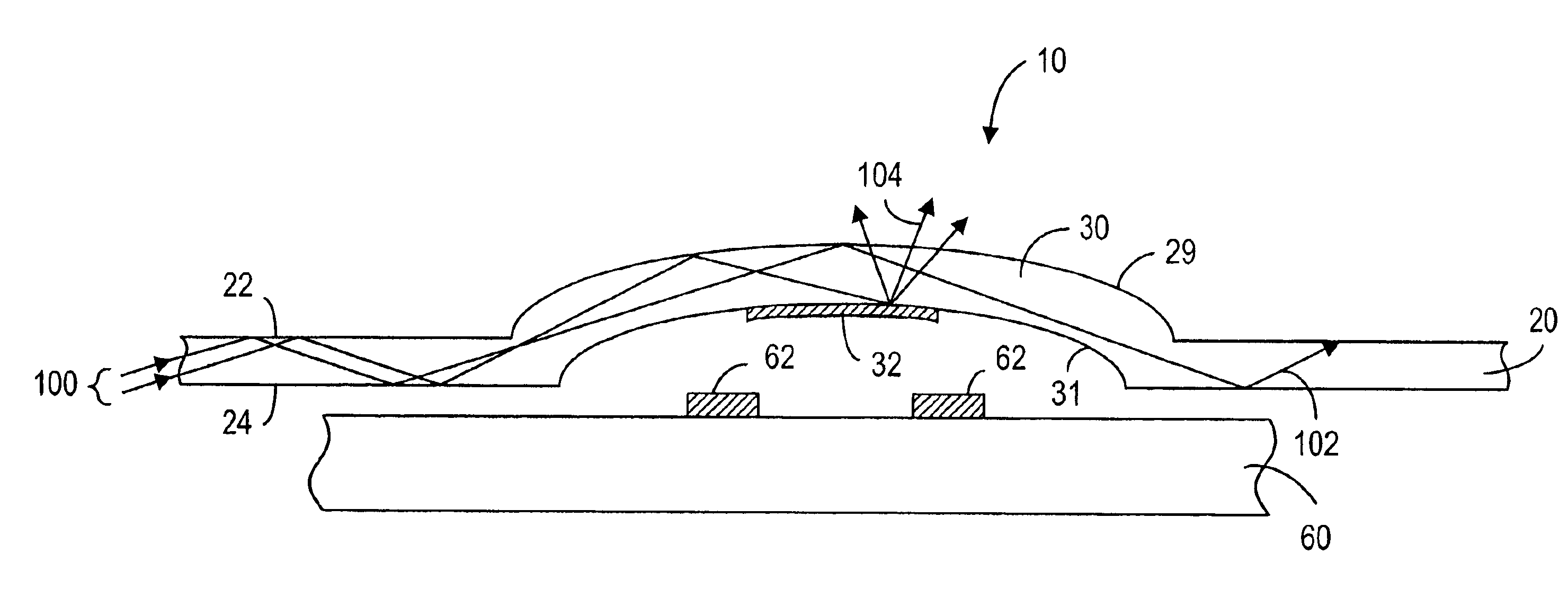
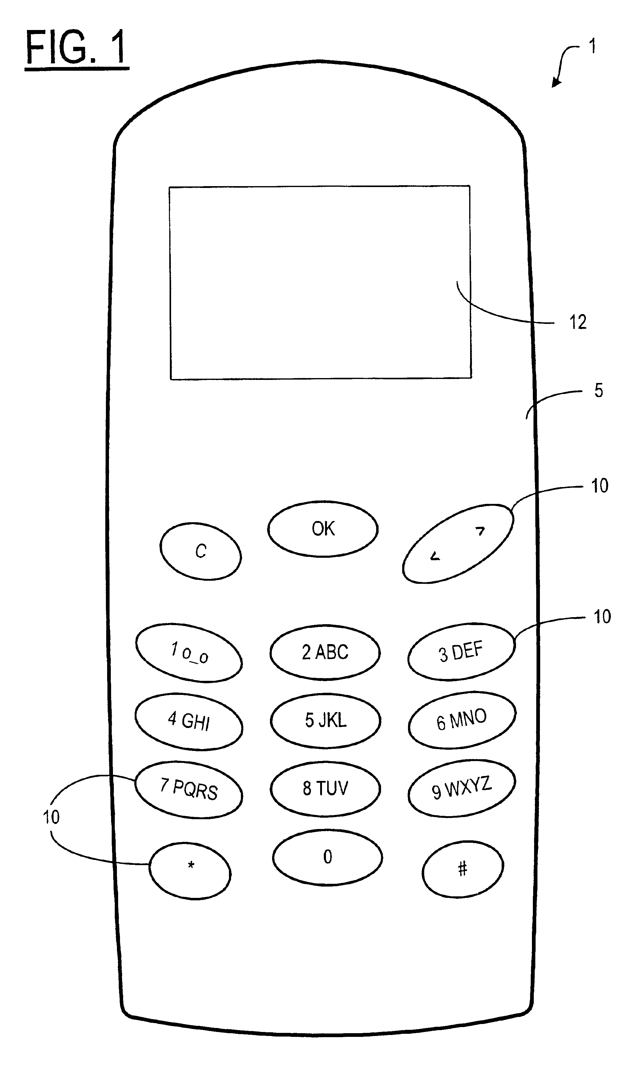
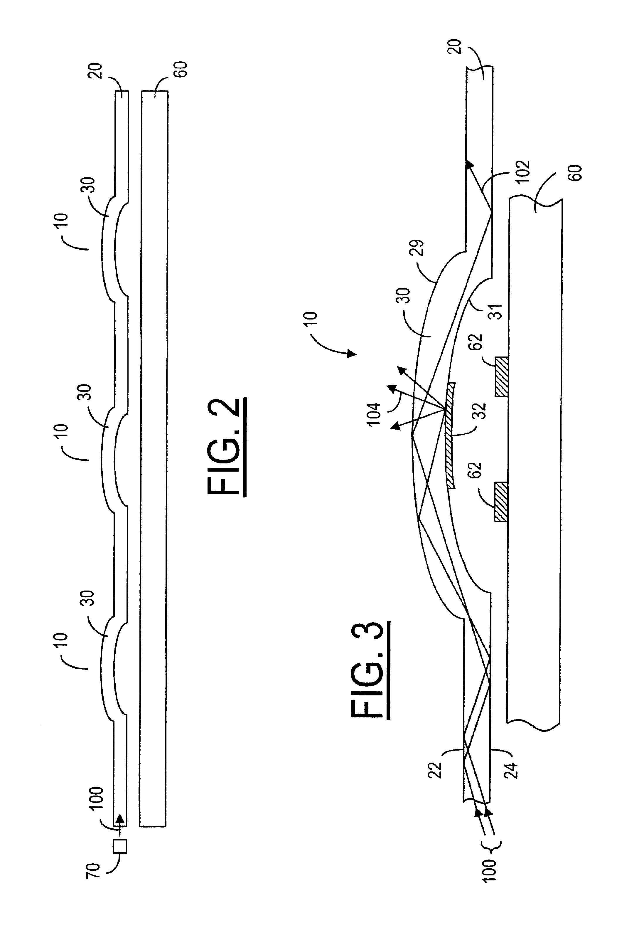
[0043]A hand-held electronic device, such as a mobile terminal 1, as shown in FIG. 1, has a cover 5 with a plurality of input keys or key buttons 10 and a display 12. It is preferred that the key buttons 10 be illuminated by an internal light source so that a user can view and use the key buttons 10 even when the natural lighting is inadequate. In order to illuminate the key buttons 10, the present invention uses a light guide 20 adapted to receiving light 100 from a light source 70, as shown in FIG. 2. The present invention integrates the light guide with a dome-sheet to provide a light dome. As shown in FIG. 2, the light guide 20 has a plurality of domes 30, which define the keys 10. The light guide 20 is disposed on top of an electronic circuit 60 in the mobile terminal 1 to allow a user to input signals to the mobile terminal 1 via the electronic circuit 60 by touching the keys 10. As shown in FIG. 3, the light guide 20 has an upper boundary interface 22 and a lower boundary int...


PUM


Abstract

An integrated light guide for use in an electronic device having a plurality of key buttons to allow a user to input signals in the device, the light guide having a plurality of domes used as touch areas of the key buttons and a plurality of light escapement areas disposed at the domes. When coupled to a light source, a portion of the light received by the light guide from the light source escapes from the light escapement areas to illuminate the key buttons. Preferably, each dome has one or more electrically conducting patches provided under the dome such that when a touch area is pushed by the user, these patches are caused to interact with an electronic circuit placed under the light guide for activating a key.

Description

FIELD OF THE INVENTION[0001]The present invention relates generally to an illumination system for illuminating the keys or push buttons on a hand-held electronic device, such as a mobile phone, and, more particularly, to a light-guide using total internal reflection to distribute light received from a light source to reach those keys and push buttons.BACKGROUND OF THE INVENTION[0002]Hand-held electronic devices, such as mobile phones, personal digital assistant (PDA) devices and Communicator devices, have an illuminated user-interface so that the user-interface can be viewed and used by a user even when natural lighting is inadequate. One of the most common ways is to use a plurality of light-emitting diodes (LEDs) to separately illuminate different areas of the user interface. The use of multiple LEDs for illumination causes a significant drain on the power source available to the electronic device. In particular, when a lambertian emitting LED is used to illuminate an area of the ...

Claims


Application Information

Patent Timeline
Patent Type & Authority Patents(United States)
IPC IPC(8): H04M1/22
CPCG06F3/0202H04M1/22
Inventor OSTERG.ANG.RD, TONIKAIKURANTA, TERHOSVARFVAR, BROR
Owner NOKIA TECHNOLOGLES OY
Why Eureka
Eureka Blog
Learn More