
Microstrip patch array antenna for suppressing side lobes

a patch array and side lobe technology, applied in the structure of individual energised antenna arrays, resonant antennas, radiating elements, etc., can solve the problem of degrading the characteristic of active phase array antennas signal leakage, and difficult to meet the strict standard of antenna radiation pattern on the side lob

Inactive Publication Date: 2005-08-02
ELECTRONICS & TELECOMM RES INST
View PDF12 Cites 4 Cited by
  • Summary
  • Abstract
  • Description
  • Claims
  • Application Information

AI Technical Summary

Benefits of technology

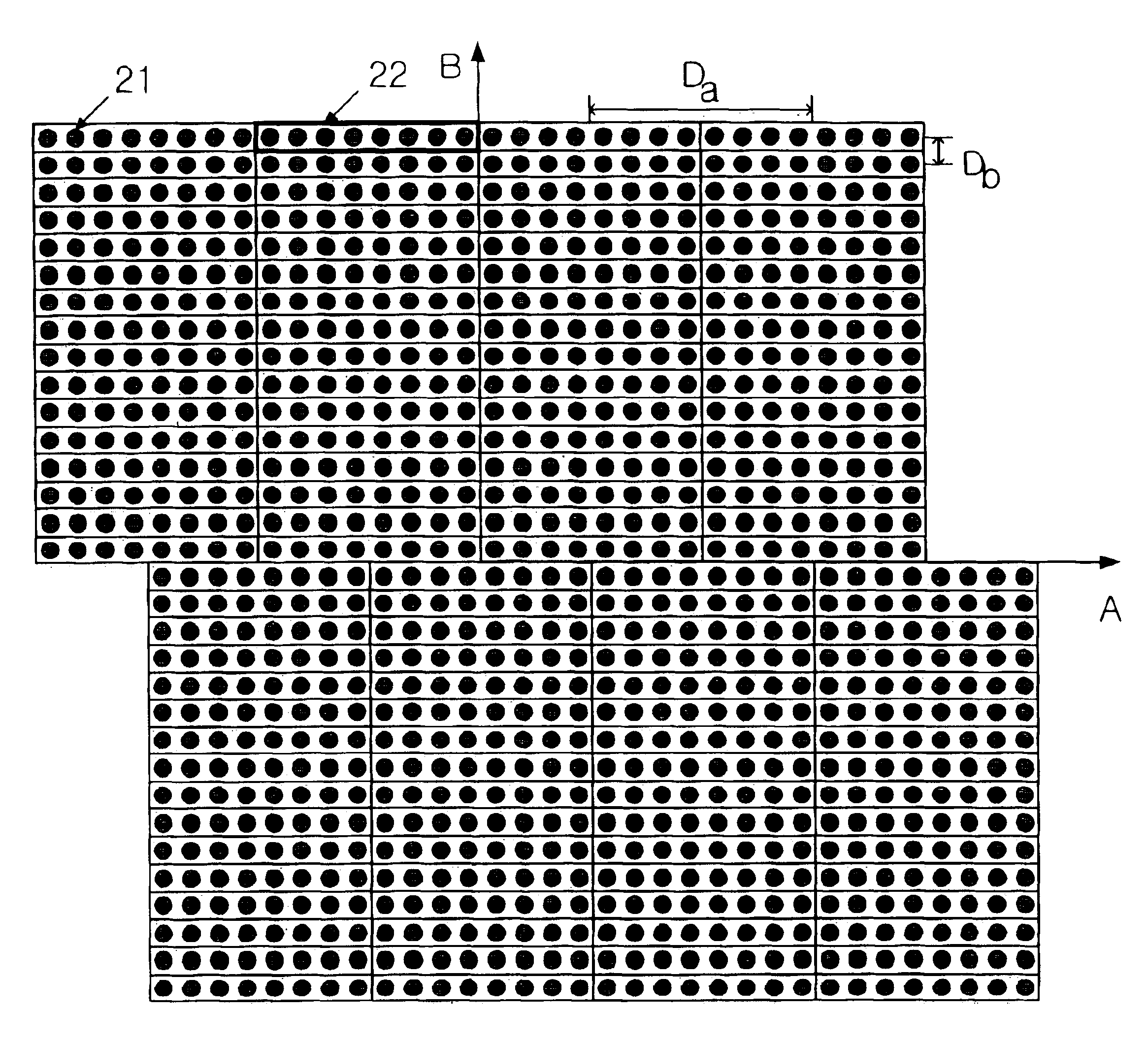
[0009]It is, therefore, an object of the present invention to provide a microstrip patch array antenna for suppressing side lobes, wherein the microstrip patch array antenna having a plurality of antenna elements, which are arranged on two dimensional rectangular planar having two axis A and B and the arranged antenna elements are divided in direction of axis B and one of divided arranged antenna elements are shifted to a direction of axis A within a predetermined spacing.
[0010]In accordance with an aspect of the present invention, there is provided a microstrip patch array antenna having a plurality of antenna array elements on two-dimensional planar having A axis and B axis for suppressing side lobes, wherein the antenna array elements are linearly arranged in a direction of the A axis by spacing a first predetermined distance between the antenna array elements, the arranged array elements are arranged in a direction of the B axis by spacing a second predetermined distance between the antenna array elements and a predetermined portion of the microstrip patch array antenna having the arranged array elements are shifted to the direction of A axis within a predetermined distance.

Problems solved by technology

However, the active phase array antenna degrades a characteristic of side lobes according to beam scan angle or antenna array grid pattern designs.
Also, the signal could be leakage.
Besides, in case the active phase array antenna using the microstrip patch array antenna is used as a portable mobile satellite antenna, it is very hard to satisfy the strict standard of the antenna radiation pattern for side lobes.
However, it is very difficult to have the spacing between array elements satisfying Eq.
Although above-mentioned, the conventional triangle grid pattern still has a problem of complexity in manufacturing, which is caused by non-continuation structure between array elements of triangular grid pattern.

Method used


Image

  • Microstrip patch array antenna for suppressing side lobes
  • Microstrip patch array antenna for suppressing side lobes
  • Microstrip patch array antenna for suppressing side lobes

Examples


Embodiment Construction

[0017]Other objects and aspects of the invention will become apparent from the following description of the embodiments with reference to the accompanying drawings, which is set forth hereinafter.

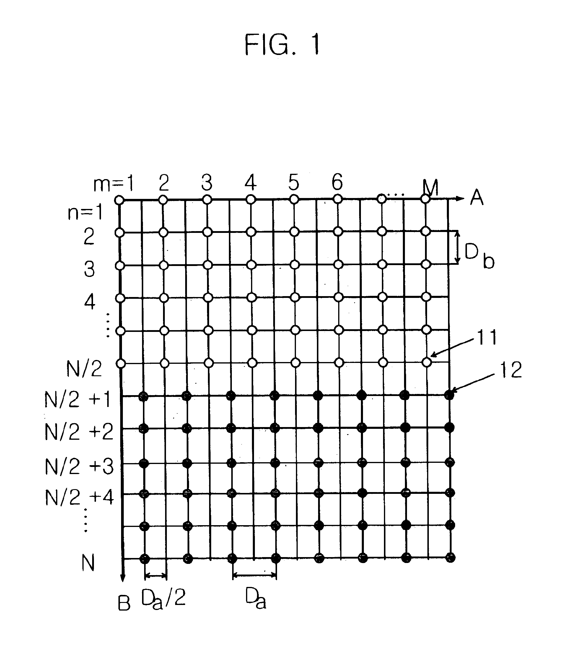
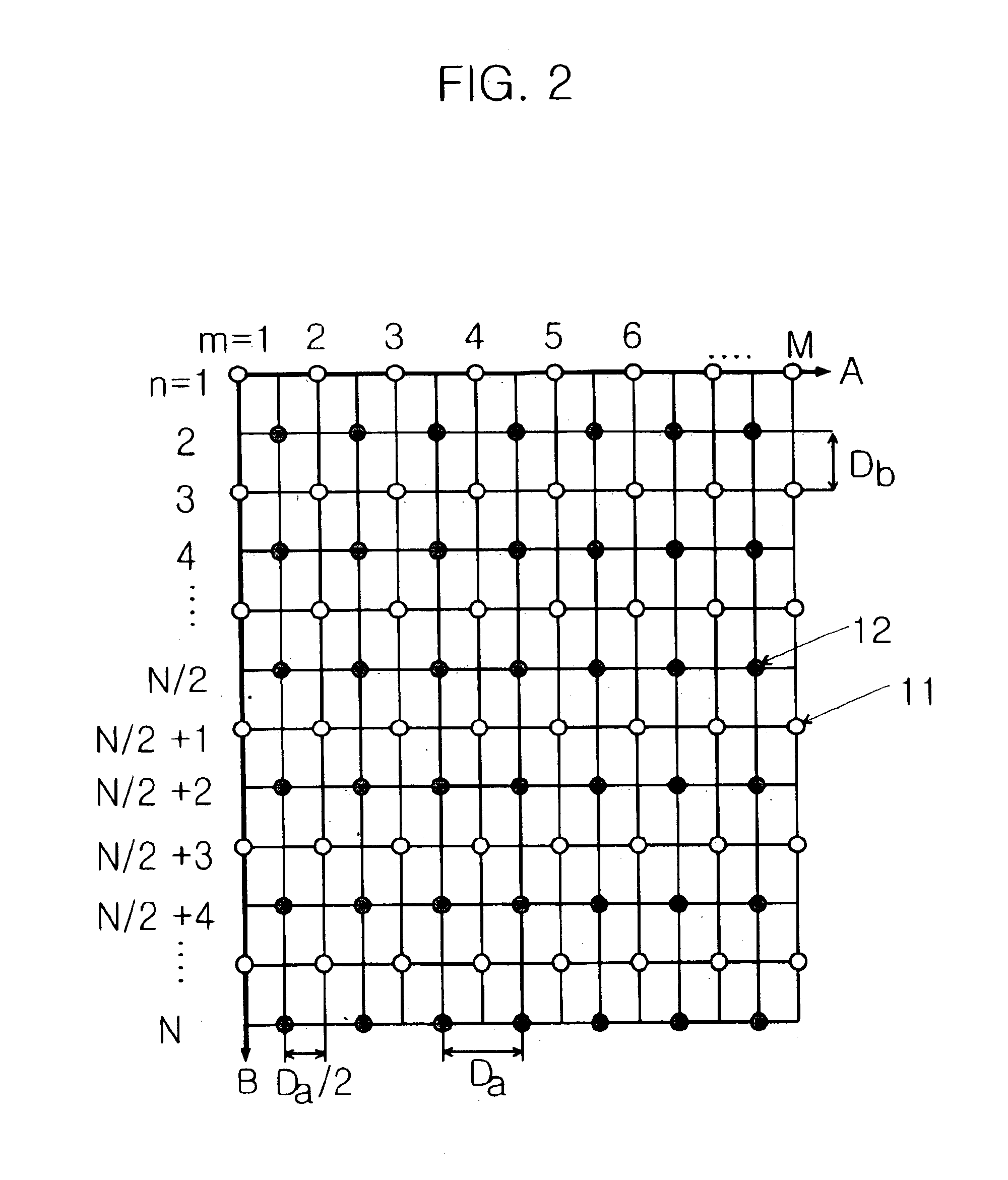
[0018]Hereinafter, the present invention is explained in detail by comparing the present invention to a conventional antenna array grid pattern as referring to FIGS. 1 and 2.

[0019]At first, array elements 11 and 12 in FIGS. 1 and 2 are compared for explaining the present invention.

[0020]FIG. 1 is a diagram for illustrating a microstrip patch array antenna having an array pattern for suppressing a side lob in accordance with a preferred embodiment of the present invention.

[0021]Referring to FIG. 1, when M integer number of antenna array elements are arranged within a spacing Da in a direction of A axis and N integer number of array elements are arranged within a spacing Db in a direction of B axis, 1 to (N / 2)th array elements in a direction of B axis are arranged a conventional rectangular a...


PUM


Abstract

A microstrip patch array antenna suppressing side lobes. The microstrip patch array antenna have a plurality of antenna array elements on two-dimensional planar having A axis and B axis for suppressing side lobes, wherein the antenna array elements are linearly arranged in a direction of the A axis by spacing a first predetermined distance between the antenna array elements, the arranged array elements are arranged in a direction of the B axis by spacing a second predetermined distance between the antenna array elements and a predetermined portion of the microstrip patch array antenna having the arranged array elements are horizontally shifted to a predetermined distance. The present invention can reduce leakage of signal or prevent to receive undesired signal and to transmit signals to undesired direction by using the above mentioned array pattern instead of reducing a distance of spacing between antenna elements.

Description

FIELD OF THE INVENTION[0001]The present invention relates to a microstrip patch array antenna; and, more particularly, to a microstrip patch array antenna having an array pattern for decreasing a grating lobe in order to suppress side lobes in an electric active phase array antenna.DESCRIPTION OF RELATED ARTS[0002]An active phase array antenna using a microstrip patch array antenna has been widely used in a satellite communication. However, the active phase array antenna degrades a characteristic of side lobes according to beam scan angle or antenna array grid pattern designs. Specially, generation of grating lobe causes to receive an undesired signal or to transmit a signal to an undesired direction. Also, the signal could be leakage.[0003]Besides, in case the active phase array antenna using the microstrip patch array antenna is used as a portable mobile satellite antenna, it is very hard to satisfy the strict standard of the antenna radiation pattern for side lobes. Therefore, fo...

Claims


Application Information

Patent Timeline
Patent Type & Authority Patents(United States)
IPC IPC(8): H01Q3/26H01Q21/22H01Q21/06H01Q13/08
CPCH01Q3/2617H01Q21/065H01Q21/22H01Q13/08
Inventor RO, HAENG SOOKJEON, SOON IKCHAE, JONG SUK
Owner ELECTRONICS & TELECOMM RES INST
Learn More