
Safety device for pressurizing an envelope at risk of bursting

a safety device and envelope technology, applied in the direction of tyres, tyre repairing, tyre measurement, etc., can solve the problems of affecting the safety of operators, so as to achieve convenient maneuverability

Inactive Publication Date: 2005-08-02
BUTLER ENG & MARKETING
View PDF16 Cites 14 Cited by
  • Summary
  • Abstract
  • Description
  • Claims
  • Application Information

AI Technical Summary

Benefits of technology

[0006]The main object of the present invention is to provide a safety device for pressurizing an envelope, typically a vehicle tire fitted onto a wheel-rim, that does not discourage the operator from using it for inflating any type of tire, thus ensuring his safety under any circumstance, if not for the fact that it is extremely handy and easy to maneuver.
[0007]Another object of the present invention is to have the said safety device operating as a verification instrument that makes it possible to obtain evidence that the same device was not actually used during inflation should a tire bursting take place.
[0008]A further object of the present invention is to provide a safety device for tire inflation that can be manufactured at very competitive production costs with respect to the costs of the safety devices currently being used.
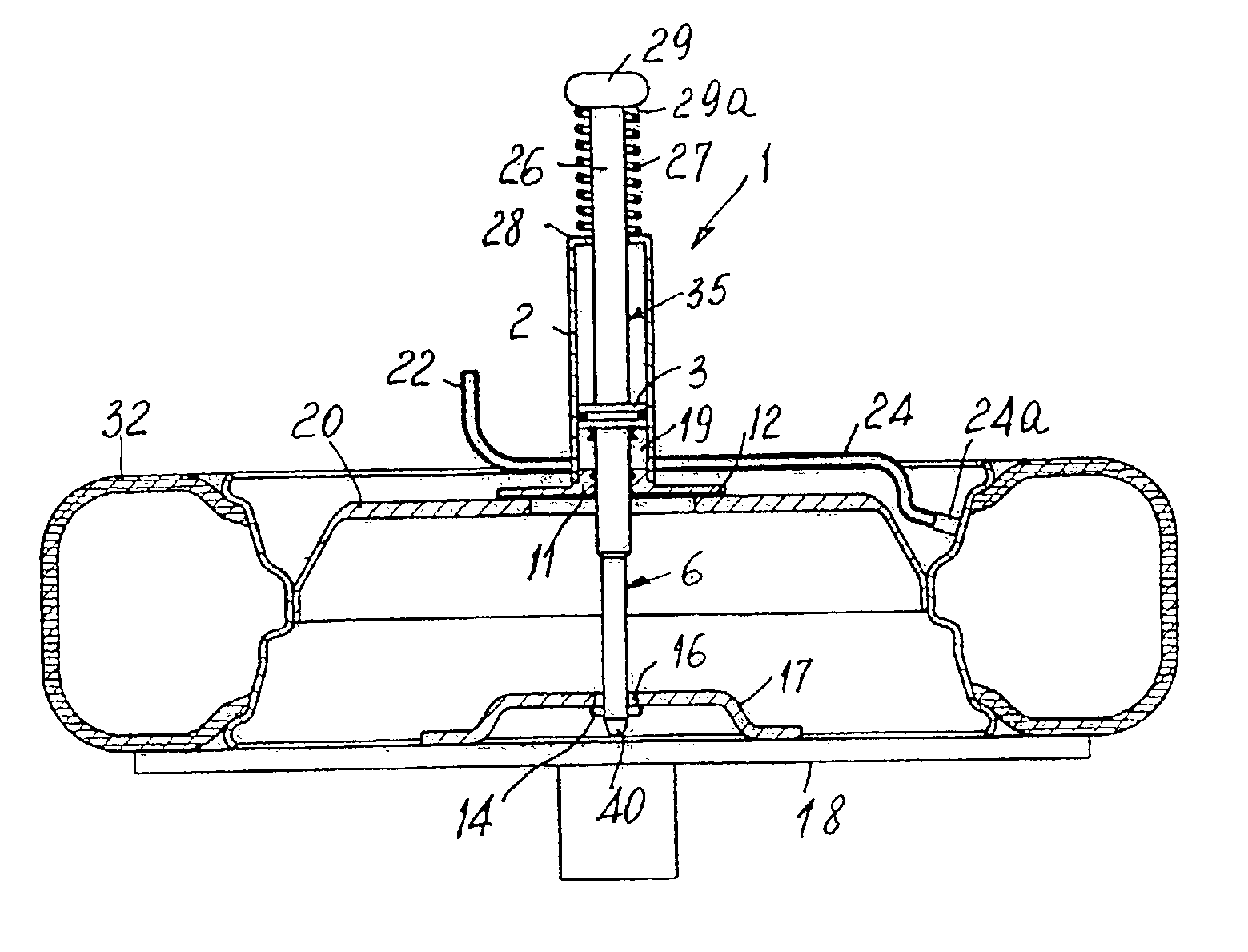
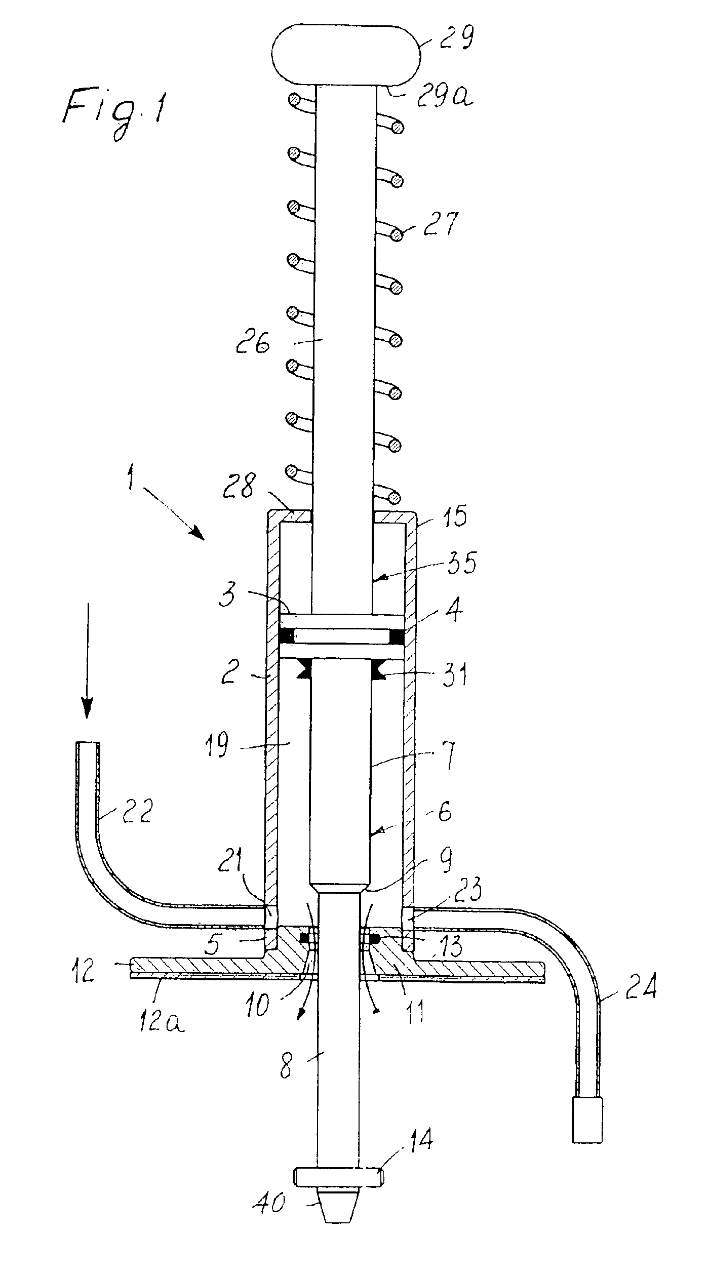
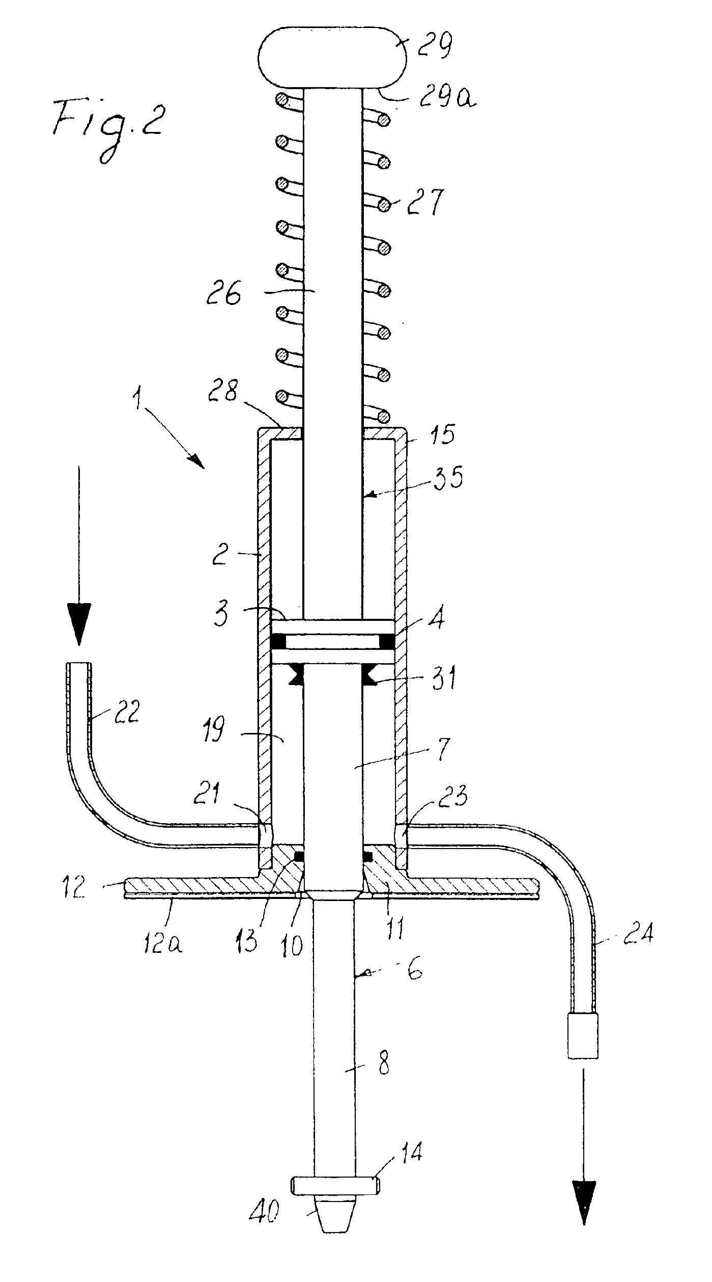
[0017]Advantageously, the specific configuration of the safety device is such that, in operation, the said annular space contains pressurized air so that a cushioning effect is exerted against the upward thrust applied to the said cylinder following an accidental bursting of the envelope.

Problems solved by technology

As the pressures involved can be relatively high, if for any reason the tire bursts, shreds of the tire and under extreme circumstances the wheel-rim itself would be thrown upwards, dramatically jeopardizing the operator's safety.
Inflation cages are themselves very effective devices, but they have the drawback to be rather cumbersome and difficult to use, as it is necessary to transfer the tire into a cage (usually manually, thus with a certain effort).
The poor practicality of such devices and above all the inertia or laziness of the operator get him to give up using them as he should, with the practical result that he is often exposed to serious safety hazards.

Method used


Image

  • Safety device for pressurizing an envelope at risk of bursting
  • Safety device for pressurizing an envelope at risk of bursting
  • Safety device for pressurizing an envelope at risk of bursting

Examples


Embodiment Construction

[0033]With reference first to the embodiment shown in FIGS. 1 to 5, it will be noted that a safety device according to the present invention, generically indicated at 1, comprises a hollow cylindrical body or cylinder 2, preferably made of steel or light alloy, within which a piston 3 is slidably mounted, around which one or more annular grooves are formed for receiving a respective sealing gasket 4. Piston 3 is provided with a first piston rod 6, which extends so far as to protrude from a first end 5 of cylinder 2 and has a predetermined minimum length, as it will be further explained below. Piston rod 6 comprises two sections having a circular cross-section but different diameters: a first section 7 with a greater diameter is connected to piston 3, whereas the second section 8, with a smaller diameter, is connected to the first section 7, preferably through an intermediate frusto-conical portion 9.

[0034]An annular bottom member 11 (hereinafter termed bottom for expediency), advant...


PUM


Abstract

A safety device for inflating an envelope at risk of bursting comprising: a tubular body, a piston element slidably and sealably mounted within at least one inner portion of the tubular body; at least one piston rod integral with the piston element and extending so as to protrude from a first end of the tubular body; an annular bottom member, located in the tubular body or at the first end of the tubular body and suitable for slidably guiding the piston rod and for closing the tubular body whereby delimiting an annular space together with the tubular body and with the piston; removable anchoring device suitable for acting at a protruding end of piston rod and for constraining the piston rod to a support; at least one inlet opening and at least one outlet opening formed in the tubular body at the annular space, in operation said inlet opening being suitable for being connected to a pressurize fluid source and the outlet opening being designed to be connected to the envelope to be pressurized; and a yielding retainer for holding in position the said piston element, so that in case of bursting, the unit formed by the tubular body and the annular bottom member can be moved longitudinally following a bursting impact with respect to the piston element in contrast with the yielding retainer.

Description

[0001]This application claims priority to Italian Application VR2001A000095 filed 04 Sep. 2001.FIELD OF THE INVENTION[0002]The present invention relates to a safety device for pressurizing and envelope at risk of bursting, particularly for inflating vehicle tires in general.BACKGROUND OF THE INVENTION[0003]Normally the inflation of a tire after fitting onto a wheel-rim is carried out by placing the wheel onto a supporting platform (usually the rotating platform of a wheel fitting machine) and blowing compressed air into a tire through the suitable inflation valve.[0004]As the pressures involved can be relatively high, if for any reason the tire bursts, shreds of the tire and under extreme circumstances the wheel-rim itself would be thrown upwards, dramatically jeopardizing the operator's safety.[0005]Until now attempts have been made to limit such a risk by resorting to devices e.g. inflation cages. Inflation cages are themselves very effective devices, but they have the drawback to...

Claims


Application Information

Patent Timeline
Patent Type & Authority Patents(United States)
IPC IPC(8): B60S5/04B60C25/00B60S5/00
CPCB60C25/00B60S5/043Y10T137/36
Inventor GONZAGA, TULLIO
Owner BUTLER ENG & MARKETING
Learn More