
Computer system employing redundant power distribution

a computer system and power distribution technology, applied in the direction of fault response, coupling device connection, instruments, etc., can solve the problems of high level, increase in the overall system size, and difficulty in cooling the additional system components

Inactive Publication Date: 2005-07-26
ORACLE INT CORP
View PDF12 Cites 25 Cited by
  • Summary
  • Abstract
  • Description
  • Claims
  • Application Information

AI Technical Summary

Benefits of technology

"The patent text describes a computer system that uses redundant power distribution. The system includes multiple circuit boards and switch circuit boards that convey information between the circuit boards. The system also includes two power distribution boards that independently distribute power to each circuit board. In one embodiment, the circuit boards are arranged in two arrays that can be detachably mated together. In another embodiment, at least two circuit boards from each array can independently distribute power to the others. The technical effect of this system is that it ensures reliable power distribution and redundancy in case of failure, which improves the overall reliability and stability of the computer system."

Problems solved by technology

Various drawbacks may be associated with systems that provide high levels of RAS capability.
Depending on the number of additional components, there may be an increase in overall system size.
In some systems, it may be difficult to cool the additional system components and thus additional air plenums may be necessary to provide an adequate flow of cooling air.
The additional plenums may also increase system size.
However, the centerplane may complicate system cooling by blocking airflow through the system boards.
Further, if the centerplane fails, it may not be replaceable without bringing down the system.
In addition, as the size and complexity of a system increases, other components of the system may also be difficult to service.
For example, if a component fails, it is sometimes necessary to remove operative components to access the failed component.
In such a case, it may be necessary to shut down one or more subsystems, which may mean losing partial or whole system functionality.

Method used


Image

  • Computer system employing redundant power distribution
  • Computer system employing redundant power distribution
  • Computer system employing redundant power distribution

Examples


Embodiment Construction

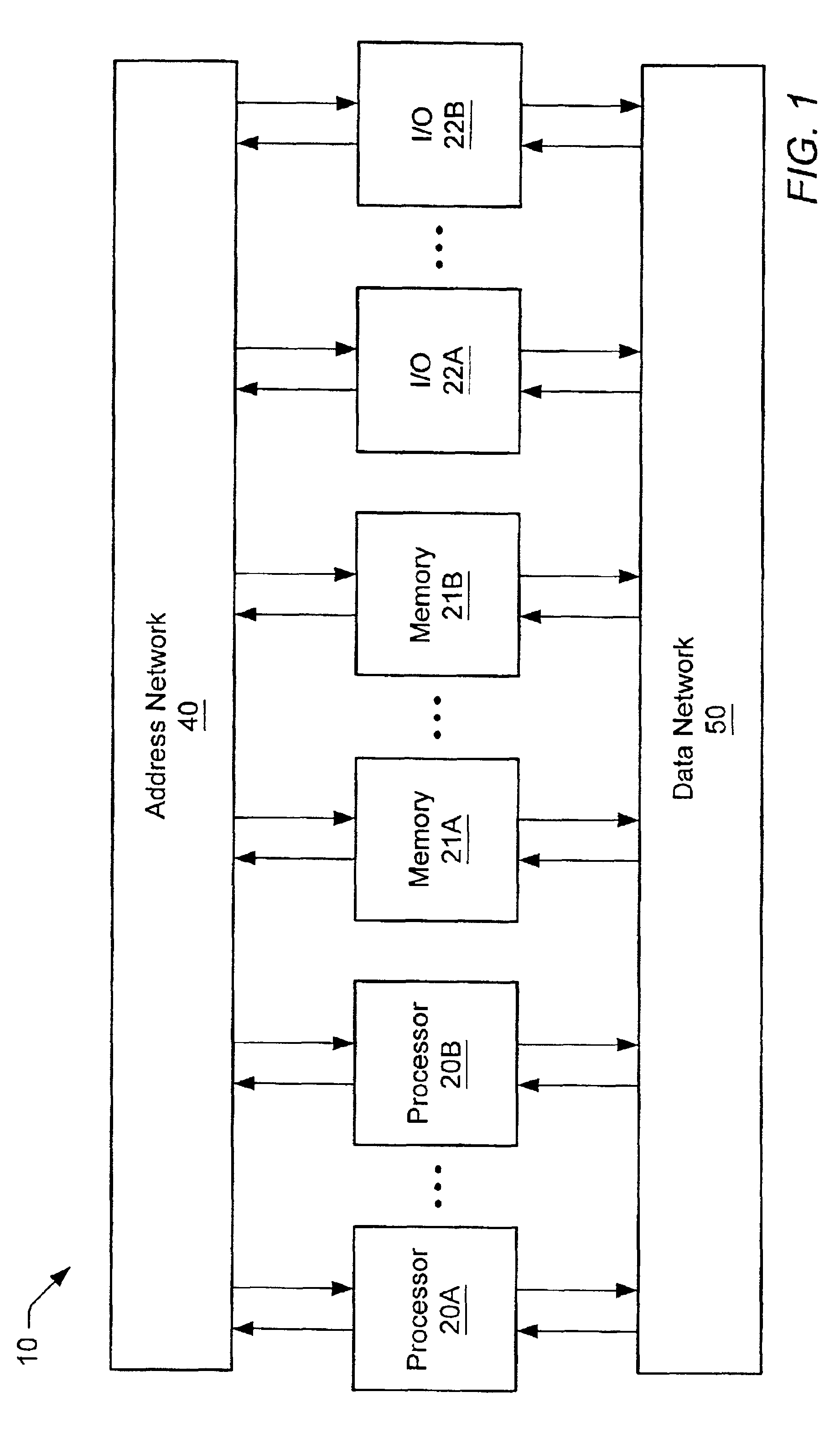
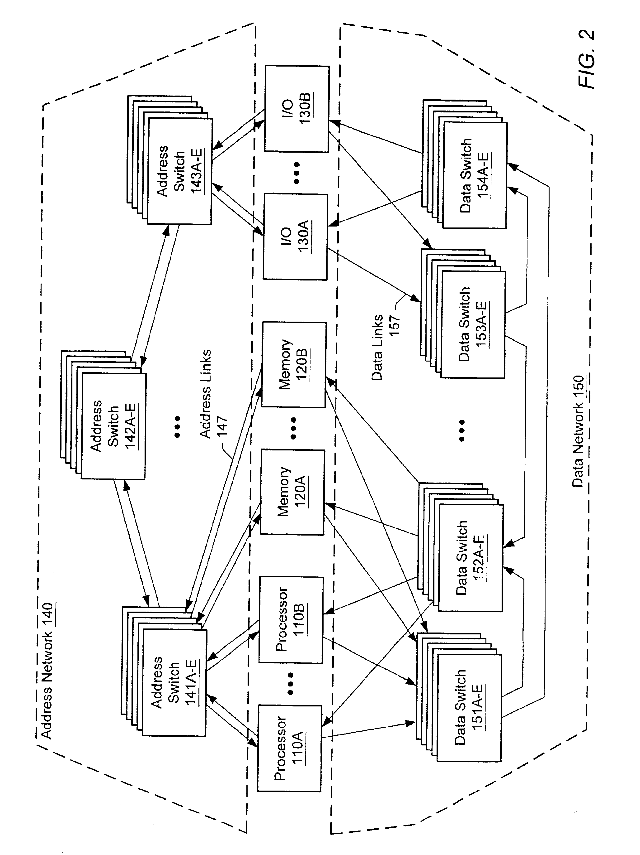
[0031]Turning now to FIG. 1, a block diagram of one embodiment of a computer system 10 is shown. Computer system 10 includes multiple client subsystems interconnected through an address network 40 and a data network 50. The embodiment of FIG. 1 may be considered a logical representation of computer system 10. The client subsystems include processor 20A and 20B, memory subsystems 21A and 21B and I / O subsystems 22A and 22B. It is noted that each of the subsystems may be referred to as a client device. It is noted that, although six client devices are shown in FIG. 1, embodiments of computer system 10 employing any number of client devices and different combinations of client device types are contemplated. Elements referred to herein with a particular reference number followed by a letter may be collectively referred to by the reference number alone. For example, processor subsystems 20A-B may be collectively referred to as processor subsystems 20. In the present embodiment, computer s...


PUM


Abstract

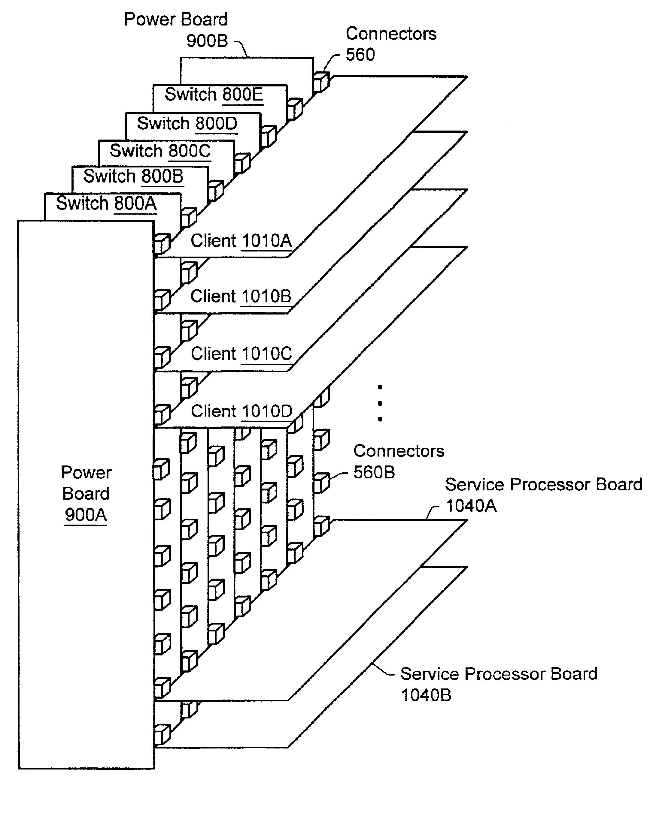
A computer system employing redundant power distribution. A computer system includes power distribution boards arranged to distribute power such that the computer system may continue to operate if there is any single point of power failure. The computer system includes a first plurality of circuit boards, a plurality of switch circuit boards and a first and second power distribution board. The plurality of switch circuit boards may be coupled to the first plurality of circuit boards and may convey address and data information between the first plurality of circuit boards. The first power distribution board and the second power distribution board may be coupled to independently distribute power to each of the first plurality of circuit boards. At least two of the first plurality of circuit boards may be coupled to independently distribute power to each of the plurality of switch circuit boards.

Description

BACKGROUND OF THE INVENTION[0001]1. Field of the Invention[0002]This invention relates to power distribution within a computer system and, more particularly, to the arrangement and connection of power distribution boards.[0003]2. Description of the Related Art[0004]Computer systems are typically available in a range of configurations which may afford a user varying degrees of reliability, availability and serviceability (RAS). In some systems, reliability may be paramount. Thus, a reliable system may include features designed to prevent failures. In other systems, availability may be important and so systems may be designed to have significant fail-over capabilities in the event of a failure. Either of these types of systems may include built-in redundancies of critical components. In addition, systems may be designed with serviceability in mind. Such systems may allow fast system recovery during system failures due to component accessibility. In critical systems, such as high-end s...

Claims


Application Information

Patent Timeline
Patent Type & Authority Patents(United States)
IPC IPC(8): G06F1/20G06F1/26G06F1/18H05K1/14G06F11/16G06F11/20
CPCG06F1/18G06F1/20G06F1/26G06F11/1016G06F11/2015G06F11/2017H05K1/14
Inventor DOBLAR, DREW G.CYPHER, ROBERT E.
Owner ORACLE INT CORP
Learn More