
Process for controlling deployment of air bag

Active Publication Date: 2005-07-26
HONDA MOTOR CO LTD
View PDF9 Cites 9 Cited by
  • Summary
  • Abstract
  • Description
  • Claims
  • Application Information

AI Technical Summary

Benefits of technology

[0009]Accordingly, it is an object of the present invention to ensure that even when the output from the load sensor is modified to the upper limit value by the limiting process, the reliable deployment of the air bag can be achieved.
[0011]With the above arrangement, in the process comprising the steps of detecting the weight of the occupant as the total of the outputs from the plurality of load sensors mounted in the seat of the vehicle, permitting the deployment of the air bag when the detected weight of the occupant is equal to or larger than the predetermined value, and prohibiting the deployment of the air bag when the detected weight of the occupant is smaller than the predetermined value, the deployment of the air bag is permitted irrespective of the detected weight of the occupant, when any one of the outputs from the plurality of load sensors is the upper limit value in the detection range. Thus, even when the output from the load sensor has been modified to the upper limit value in the detection range by a limiting process, so that the weight of the occupant is calculated as a value smaller than an actual weight to become smaller than the predetermined value, the air bag can be deployed reliably to restrain the occupant.

Problems solved by technology

However, such an output from each of the load sensors has an upper limit value and a lower limit value.
Therefore, when an adult or child is on the seat, there is a possibility that the air bag, which should be naturally deployed, is not deployed.
Therefore, there is a possibility that the status is erroneously judged as the child seat although the status is actually an adult or child, whereby the deployment of the air bag which should be naturally deployed is prohibited.

Method used


Image

  • Process for controlling deployment of air bag
  • Process for controlling deployment of air bag
  • Process for controlling deployment of air bag

Examples


Embodiment Construction

[0019]The present invention will now be described by way of a preferred embodiment with reference to the accompanying drawings.

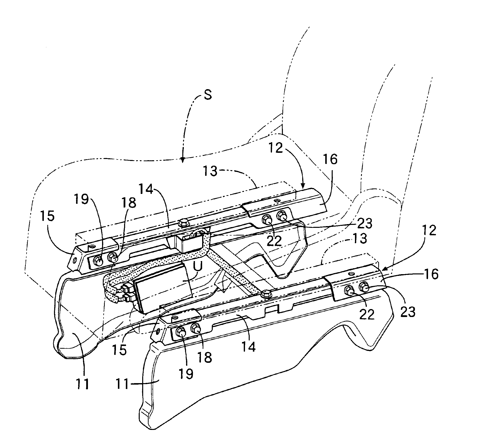
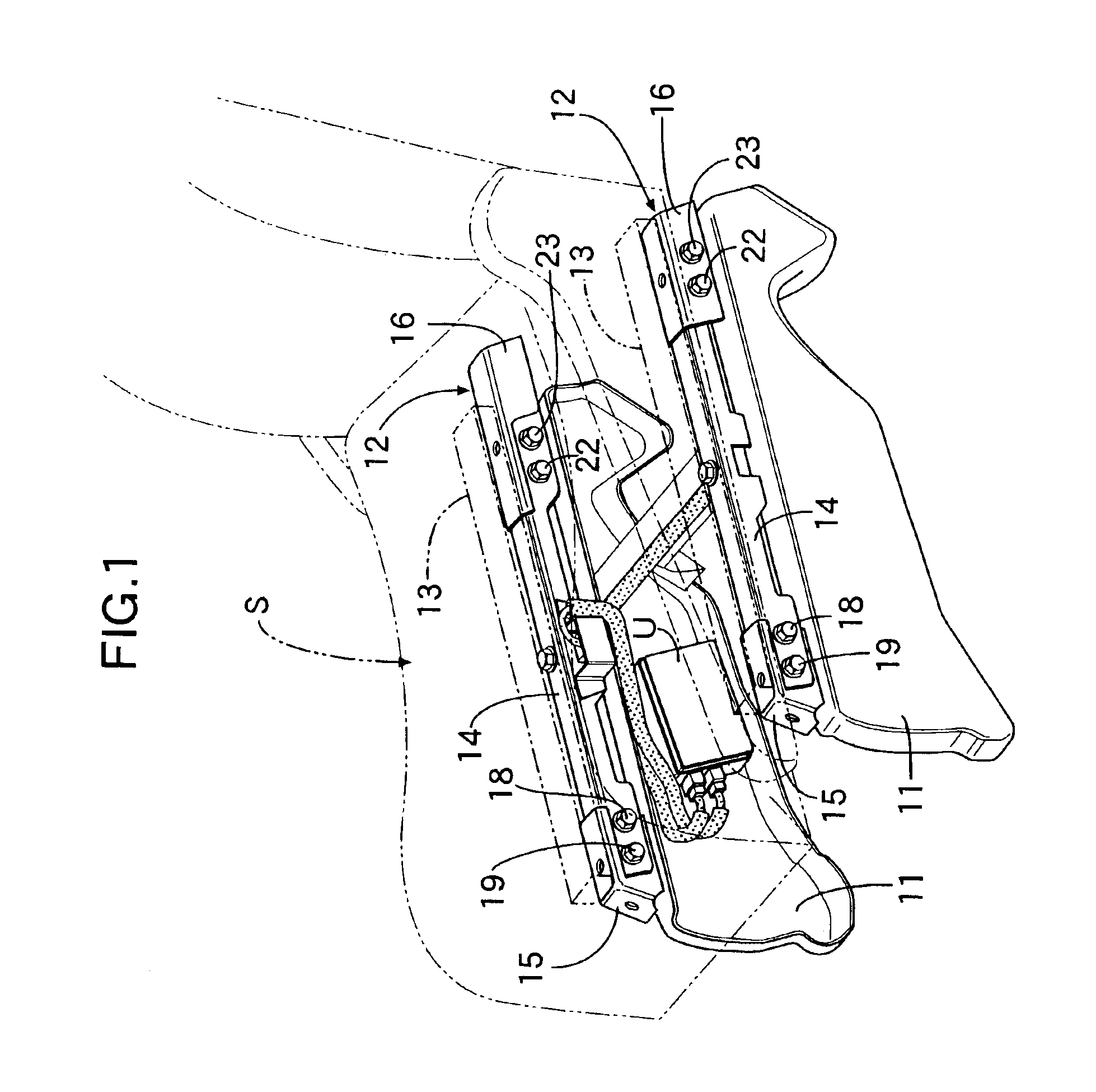
[0020]Referring first to FIG. 1, a pair of left and right base members 11, 11 are fixed to a floor of an automobile. A pair of left and right weight-detecting units 12, 12 are mounted along upper surfaces of the base members 11, 11, respectively. A seat S is longitudinally movably supported on a pair of left and right seat rails 13, 13 fixed to upper surfaces of the weight-detecting units 12, 12.

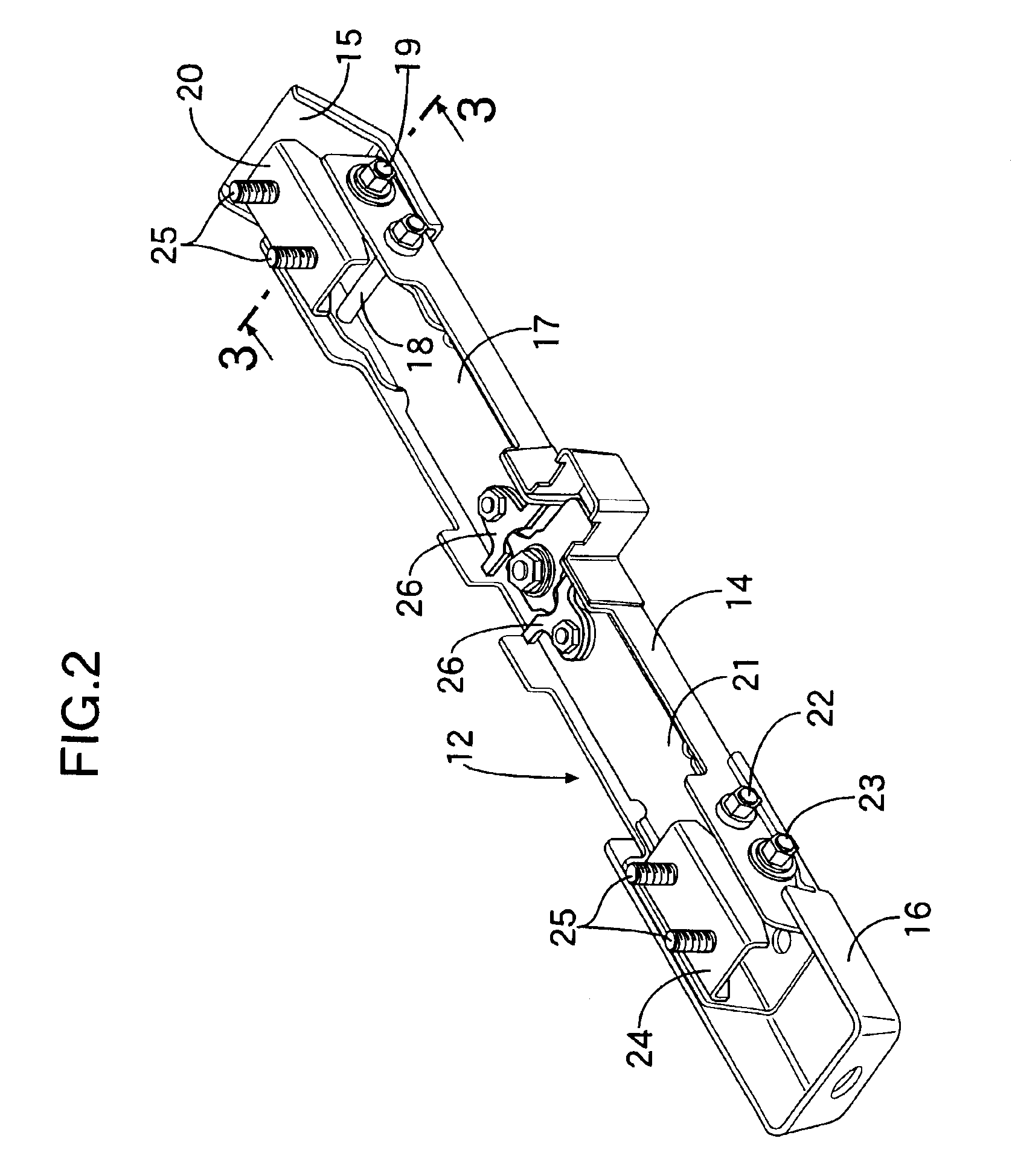
[0021]FIG. 2 shows the weight-detecting unit 12 in a state viewed from the side of its lower surface. The left and right weight-detecting units 12, 12 have substantially the same structure, and one of the weight-detecting units 12, 12 is shown in FIG. 2.

[0022]The weight-detecting unit 12 includes a sensor housing 14 having a groove-shaped section with its lower surface opened. Front and rear brackets 15 and 16 to which the seat rail 13 is coupled, are mounted at fron...


PUM


Abstract

Four load sensors having an upper limit value in a detection range are mounted in a seat of a vehicle. The weight of an occupant sitting on the seat is detected as a total of outputs from the load sensors. When the detected weight of the occupant is equal or larger than a predetermined value, the deployment of the air bag is permitted, and when the detected weight of the occupant is smaller than the predetermined value, the deployment of the air bag is prohibited. When any one of the outputs from the plurality of load sensors is the upper limit value in the detection range, the deployment of the air bag is permitted irrespective of the detected weight of the occupant. Thus, even when the output from the load sensor has been modified to the upper limit value by a limiting process, so that the weight of the occupant is calculated as a value smaller than an actual weight to become smaller than the predetermined value, the air bag can be deployed reliably to restrain the occupant.

Description

BACKGROUND OF THE INVENTION[0001]1. Field of the Invention[0002]The present invention relates to a process for controlling deployment of an air bag, comprising the steps of preparing a plurality of load sensors mounted in a seat of a vehicle and having an upper limit value in a detection range, detecting the weight of an occupant sitting on the seat as a total of outputs from the sensors, permitting the deployment of the air bag when the detected weight of the occupant is equal or larger than a predetermined value, and prohibiting the deployment of the air bag when the detected weight of the occupant is smaller than the predetermined value.[0003]2. Description of the Related Art[0004]The operation or non-operation of an air bag device for an assistant driver's seat, the deployment speed of an air bag and the like are controlled depending on the physical constitution and the presence or absence, i.e., the status of an occupant sitting on the assistant driver's seat. For example, if t...

Claims


Application Information

Patent Timeline
IPC IPC(8): B60R21/01G01G19/12B60N2/90B60R21/015B60R21/16B60R21/33G01G19/52
CPCB60R21/01516B60R21/33
Inventor KOJIMA, MIKIHITOSHINDO, TOYOHIKONAGAI, MAKOTO
Owner HONDA MOTOR CO LTD
Learn More