
Brake shoe for sash window or door assembly

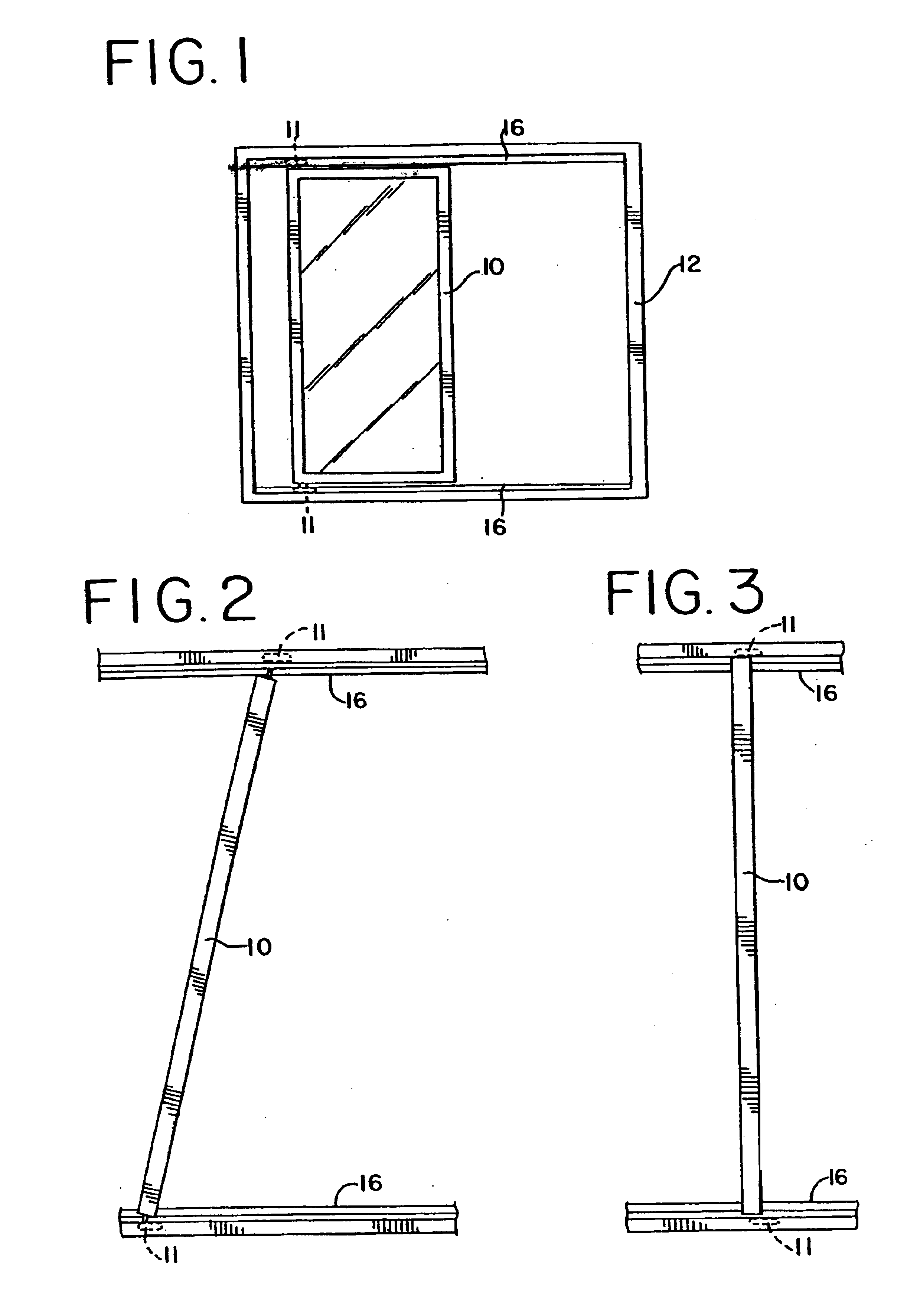
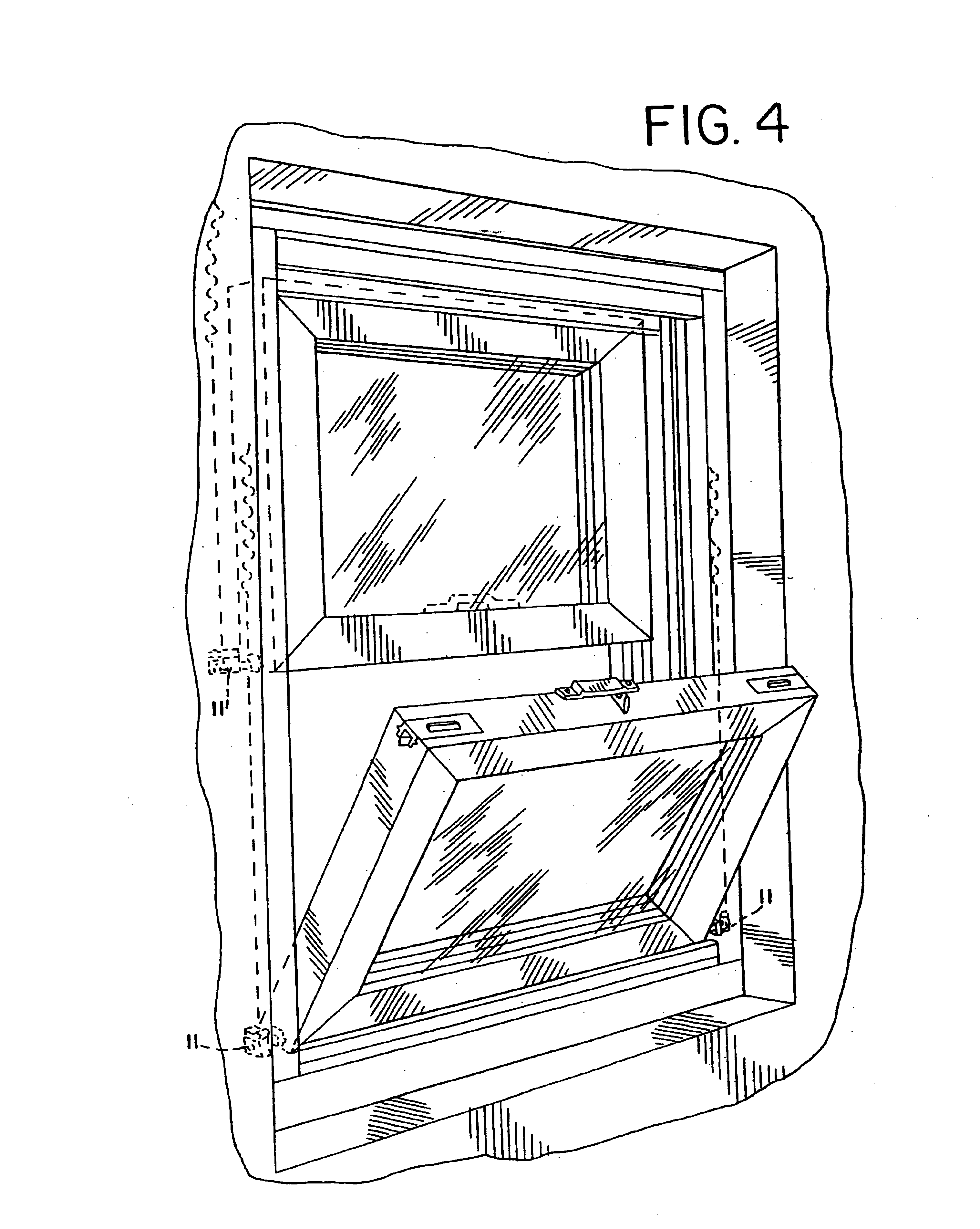
a technology for sash windows and doors, applied in the direction of door/window fittings, construction fastening devices, construction, etc., can solve the problem that the pivot arrangement of this type may not develop adequate arresting strength and reliability

Inactive Publication Date: 2005-07-12
ASHLAND HARDWARE LLC
View PDF64 Cites 10 Cited by
  • Summary
  • Abstract
  • Description
  • Claims
  • Application Information

AI Technical Summary

Benefits of technology

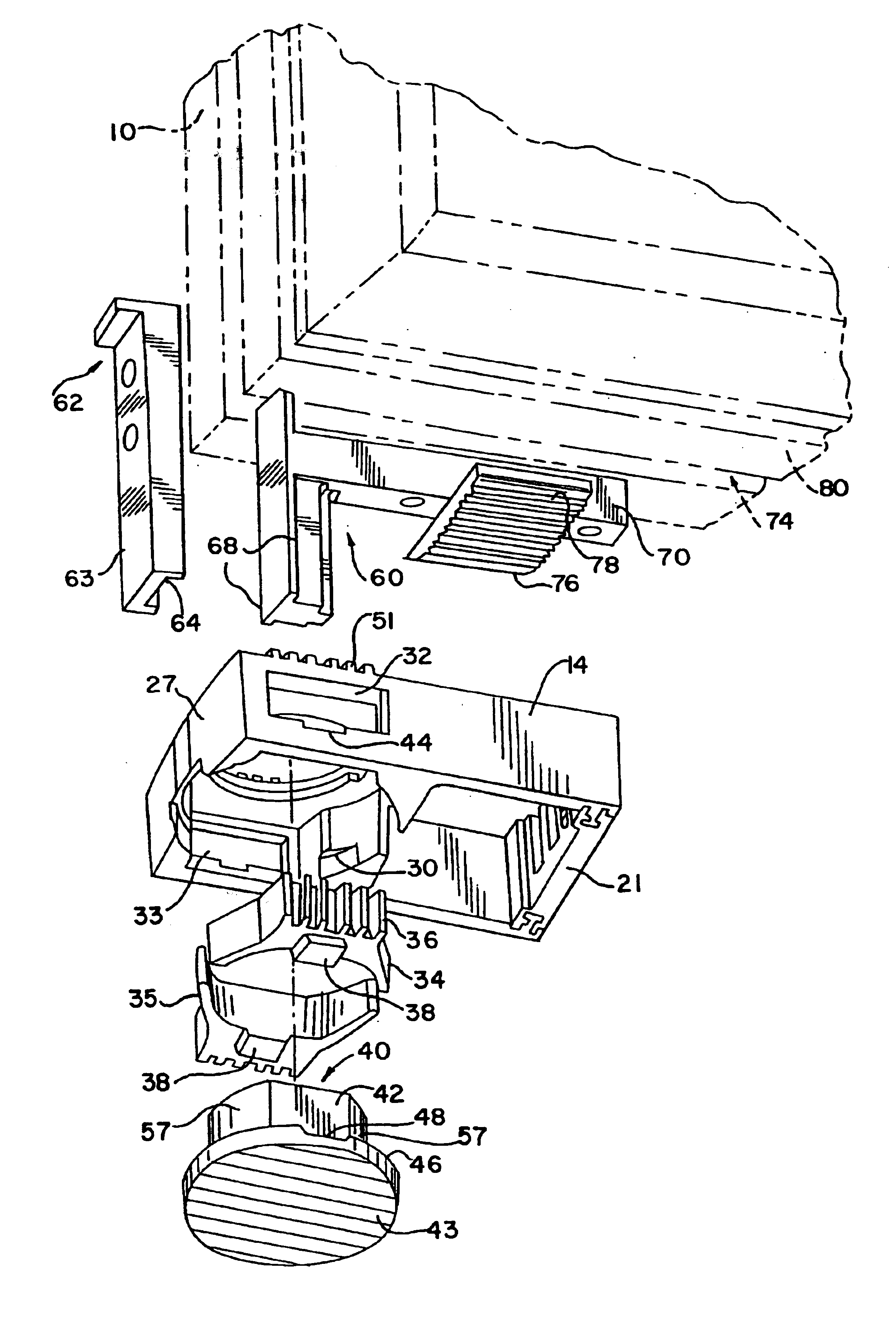
[0007]According to a first aspect of the invention, a sash balance brake assembly is disclosed for locking a slidable sash window or door within a track of a frame, the track having an elongated base and a pair of spaced apart, opposed sidewalls extending perpendicular from the base, each sidewall having an inner shoulder spaced from and parallel to the base. The assembly has a slider body having a central opening extending from a front face of the body to a rear face of the body, a pair of side openings in the slider body being in communication with the central opening. A brake member is slidably positioned within each side opening. A cam is provided having a rear f...

Problems solved by technology

Although simple to operate, experience has shown that a pivot arrangement of this type may not develop adequate arresting strength and reliability.

Method used


Image

  • Brake shoe for sash window or door assembly
  • Brake shoe for sash window or door assembly
  • Brake shoe for sash window or door assembly

Examples


second embodiment

[0055]A second preferred embodiment of the present invention is depicted in FIGS. 20-26. Elements of this second embodiment that are similar in structure and function to corresponding elements of the first described embodiment will be referred to with identical reference numerals.

[0056]In this second preferred embodiment, the brake shoe assembly 11 utilizes an integral brake shoe element. The radial or lateral brake members 34 are connected by a first, upper resiliently flexible member 239 and a second, or lower resiliently flexible member 241. The integral brake element consisting of brake members 34,35 and flexible members 239,241 is mounted in the slider body 14 such that the brake members 34 are slidably located in the side openings 32,33 and such that the flexible members 239,241 are located within the central opening 28. The cam mechanism 40 is mounted within the central opening 28 such that the flexible members 239 generally surround the cam mechanism 40.

[0057]In operation, t...

third embodiment

[0061]The freely-slidable window position of the third embodiment is defined as that position wherein the cam flats 42 abut the flat portions 47 of brake members 34,35, depressions 340 receive the cam radial protuberances 341 and cam flange recesses 48 receive brake member protrusions 38. As shown in FIG. 28, when the cam is rotated as previously described, the cam radial protuberances 341 leave the depressions 340 and engage the flat surfaces 47 of the brake members 34,35 to bias the brake members 34,35 for radial movement, thus resulting in frictional engagement of frictional ribbed surfaces 36 with opposed side walls 20 of track 16. Upon further cam 40 rotation, circular portions 57 of cam 40 engage the flat portions 47 of brake members 34,35 thereby continuing to bias the brake members 34,35 for additional and greater frictional engagement of ribbed surfaces 36 with opposed side walls 20 of track 16. Substantially simultaneous with this radial biasing of brake members 34,35, rot...


PUM


Abstract

A brake assembly for locking a vertical or horizontal slidable sash window or door within a track of a frame is disclosed. The track has an elongated base and a pair of spaced apart, opposed sidewalls extending perpendicular from the base. Each sidewall has an inner shoulder spaced from and parallel to the base. The assembly has a slider body having a central opening extending from a front face of the body to a rear face of the body. The slider body has a side opening in each side of the slider body and being in communication with the central opening. A pair of brake members are provided wherein one brake member is slidably positioned within a respective one of the side openings. A cam has a rear face and a front face, and is adapted to receive a pivot member mounted on either the sash window or door. The cam is positioned in the central opening and is adapted to be rotatable within the opening by the pivot member. The cam, slider body and brake members include cooperative structure for converting rotary motion of the cam into radial movement of the brake members through the side openings and axial movement of the cam and slider body to lock the brake assembly within the track.

Description

RELATED APPLICATIONS[0001]This application is a continuation of and claims the benefit of application No. 09 / 780,917, filed Feb. 9, 2001, now U.S. Pat. No. 6,550,184, which is expressly incorporated by reference herein and made a part hereof.TECHNICAL FIELDBackground of the Invention[0002]It is known in the prior art of slidable window sash and frame construction to have vertical and horizontal sliding windows adapted to be pivoted out of the frame when desired. For tasks such as cleaning the window from within the building in which the window is installed, a pivoting window must be securely arrested from sliding at the pivot point to prevent sagging or complete dislodging of the sash from the frame.[0003]Pivot mechanisms have included movable pins mounted on the edge of the sash which may be extended outwardly to engage holes in the frame about which the sash may be pivoted. U.S. Pat. No. 4,222,201 discloses a pivoting mechanism wherein a pair of spring biased pins are manually ext...

Claims


Application Information

Patent Timeline
IPC IPC(8): E05D15/22E05D15/16E05C17/00E05C17/64E05D15/00E05D15/58
CPCE05D13/08E05D15/0604E05D15/22E05D15/58E05D2015/586E05Y2201/21E05Y2201/232E05Y2201/26E05Y2201/264E05Y2201/64E05Y2800/744E05Y2900/148E05Y2900/132
Inventor O'DONNELL, RICHARD H.ANNES, JASON L.
Owner ASHLAND HARDWARE LLC
Learn More