
Ion trap

a technology of ion traps and electrodes, applied in the field of electromechanical structure and geometry of ion traps, can solve the problems of unintentional degradation of field, shift in measured ion mass from theoretical mass value, and increase in the peak of the field,

Inactive Publication Date: 2005-06-28
THERMO FINNIGAN
View PDF5 Cites 25 Cited by
  • Summary
  • Abstract
  • Description
  • Claims
  • Application Information

AI Technical Summary

Problems solved by technology

In the context of mass spectrometry using quadrupole ion traps, the field faults can result in both peak broadening and, in some cases, a shift in the measured ion mass from the theoretical mass values.
However, the overall improvement in the field linearity with the prior art methods can not be obtained without an unintentional degradation of the field in localized areas (e.g., at key locations between the trap center and the apertures in the vicinity of 60-70% of the distance therebetween).

Method used


Image

  • Ion trap
  • Ion trap
  • Ion trap

Examples


Embodiment Construction

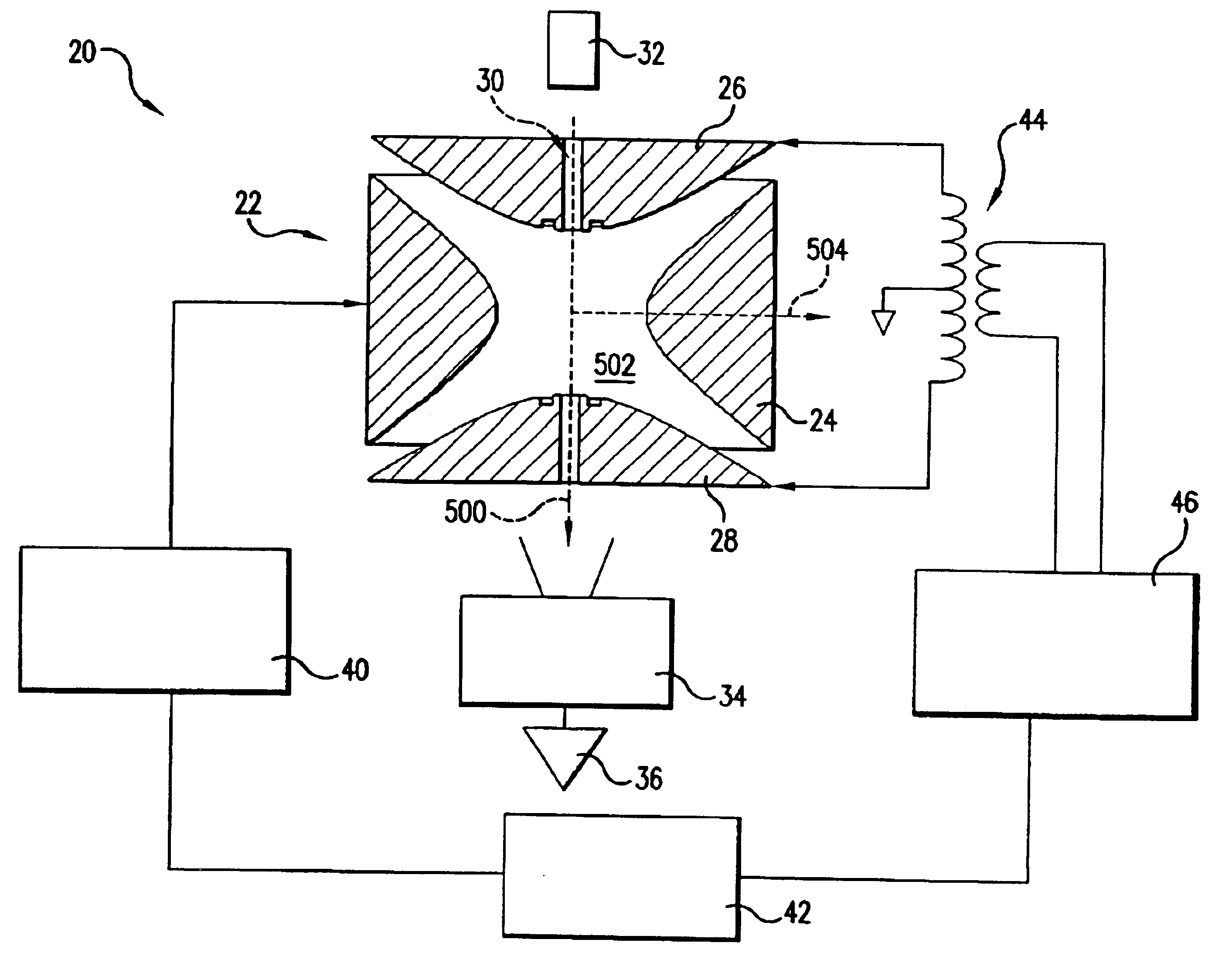
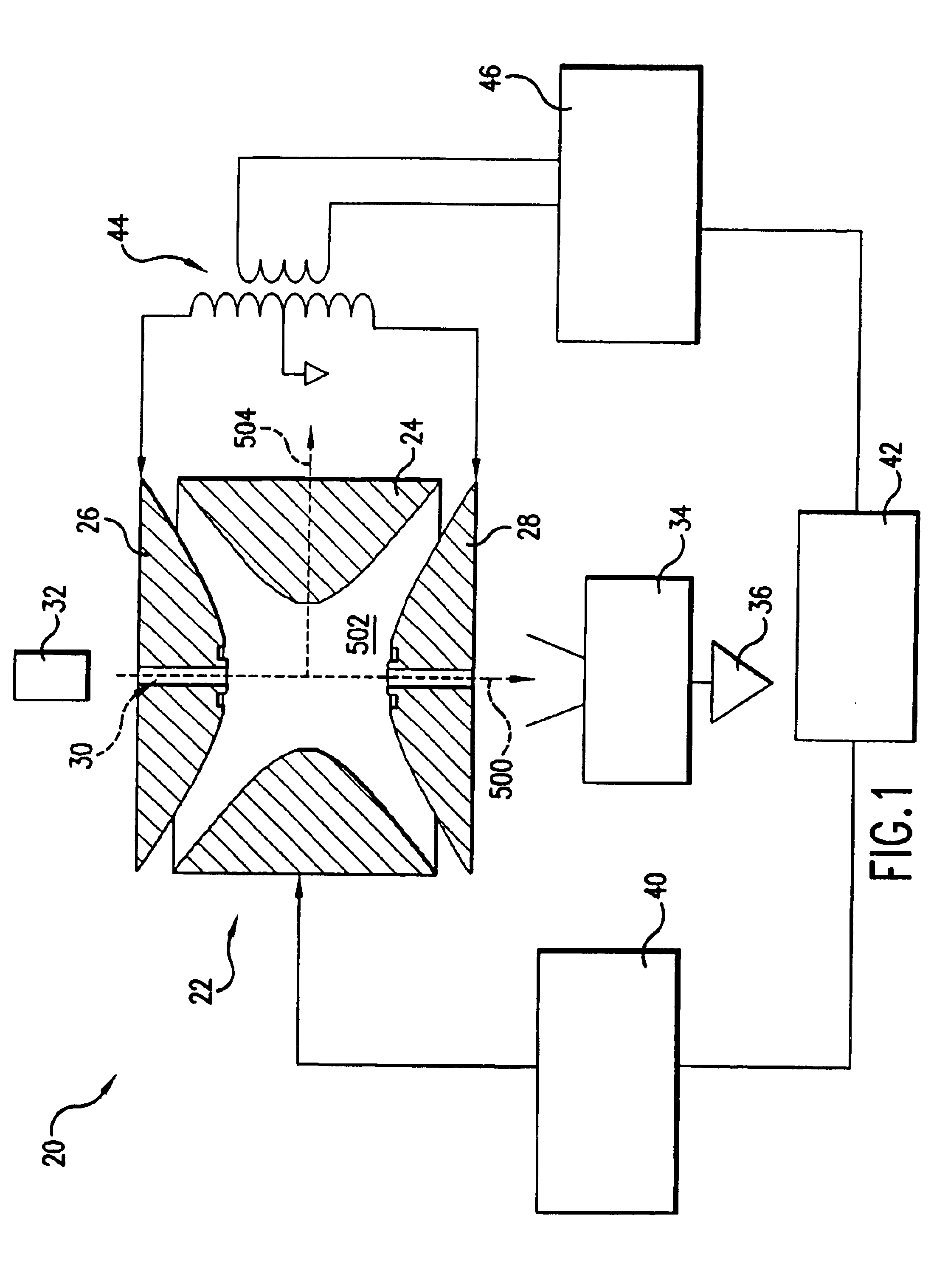
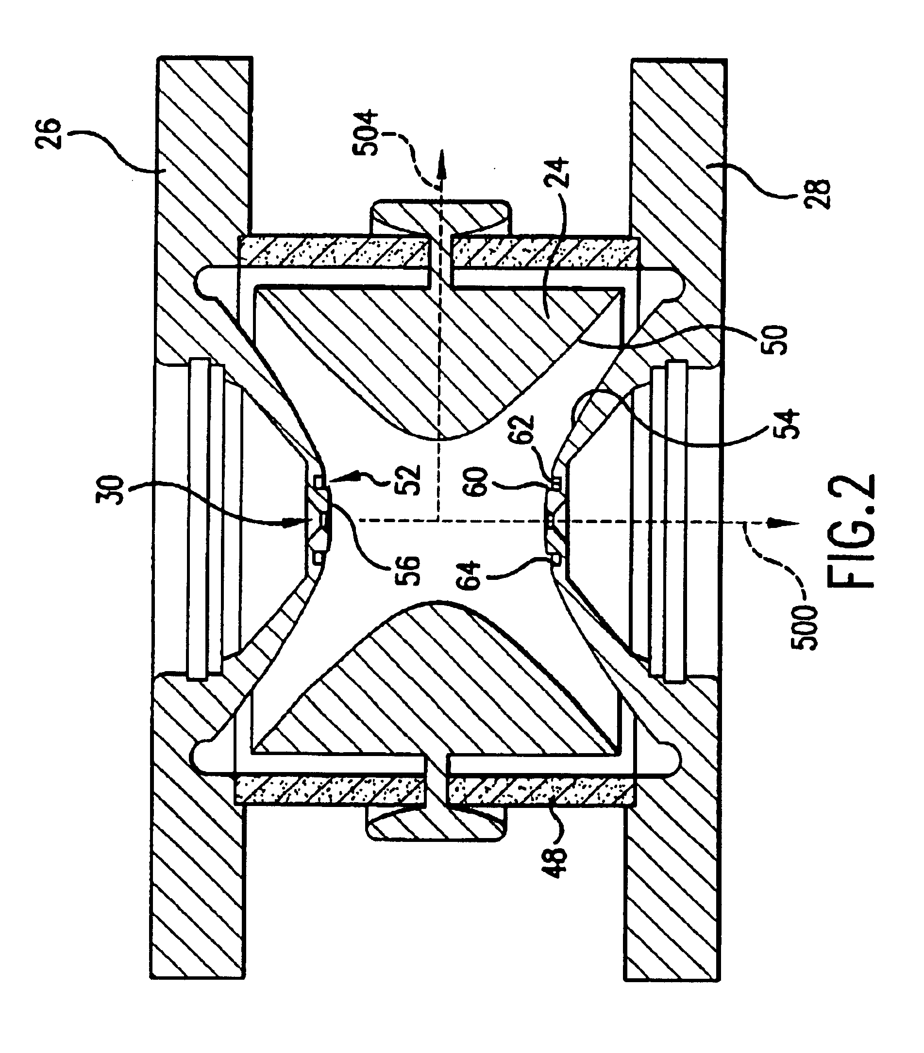
[0026]FIG. 1 shows a quadrupole ion trap mass spectrometer 20 that includes an ion trap 22 having a ring electrode 24 and first and second end cap electrodes 26 and 28. The ion trap has a central longitudinal axis 500 that is conventionally designated the Z-axis having an origin centrally within a trapping volume 502 in the trap interior. A radial direction 504 is shown extending from the origin. Each end cap electrode 26, 28 has a central aperture or channel 30. An electron gun 32 may inject electrons through the aperture 30 of the first (inlet) electrode 26 into the ion trap to ionize a sample. Alternatively, the sample may be ionized externally and the ions injected into the trap through that aperture. In either event, ions of interest are introduced into the trap. Such ions may escape the trapping volume space 502 through the aperture 30 of the second (outlet) electrode 28. These ions are then detected by the electron multiplier 34. The output of the electron multiplier is pre-a...


PUM


Abstract

There is provided a quadruple ion trap (22) of the type including a ring electrode (24) and first and second end cap electrodes (26, 28), which define a trapping volume. The end cap electrodes (26, 28) include central apertures (30) for the injection of ions or electrons into the trapping volume and for the ejection of stored ions during the analysis of a sample. Field faults in the RF trapping field are compensated by addition of a concentric recess or depression in the surface of at least one end cap (26, 28) around the aperture (30). There is also provided an ion trap mass spectrometer employing the ion trap.

Description

CROSS-REFERENCE TO RELATED APPLICATION[0001]“This patent application is the U.S. national phase of International Patent Application Ser. No. PCT / US02 / 14490, entitled “ION TRAP”, that was filed on May 8, 2002 and published in English on Nov. 14, 2002 as International Publication No. WO 02 / 091427, and claims priority of U.S. Provisional Patent Application Ser. No. 60 / 289,657 entitled “Quadrupole Trap with Improved Fields” filed May 8, 2001, the disclosure of which is incorporated by reference herein in its entirety.”BACKGROUND OF THE INVENTION[0002](1) Field of the Invention[0003]This invention relates to the electrode structure and geometry of ion traps in general and to quadrupole ion traps and associated mass spectrometers in particular.[0004](2) Description of the Related Art[0005]The ion trap of an ion trap mass spectrometer, in its most common configuration, is composed of a central ring electrode and two end cap electrodes (end caps). Generally, in longitudinal section, each el...

Claims


Application Information

Patent Timeline
Patent Type & Authority Patents(United States)
IPC IPC(8): H01J49/34H01J49/00H01J49/42
CPCH01J49/4225H01J49/4255H01J49/424H01J49/423
Inventor SENKO, MICHAEL W.SCHWARTZ, JAE C.
Owner THERMO FINNIGAN
Learn More