
Computed tomography gantry cooling systems and methods

a cooling system and computed tomography technology, applied in the field methods, can solve the problems of generating a significant amount of heat during normal operation, reducing the efficiency of computed tomography systems, and reducing the noise of the overall ct system, so as to reduce the overall noise of the ct system and increase the cooling efficiency

Inactive Publication Date: 2005-06-21
GENERAL ELECTRIC CO +1
View PDF6 Cites 33 Cited by
  • Summary
  • Abstract
  • Description
  • Claims
  • Application Information

AI Technical Summary

Benefits of technology

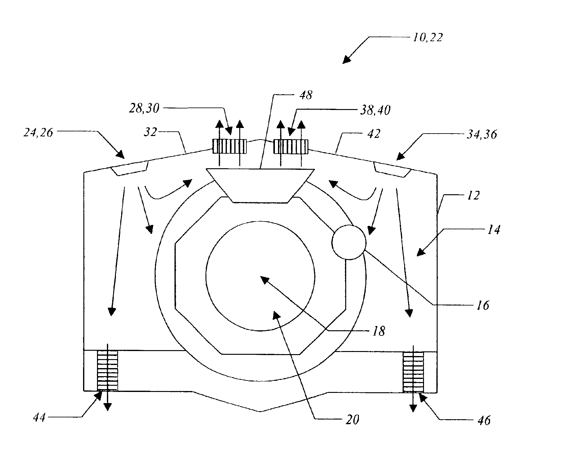
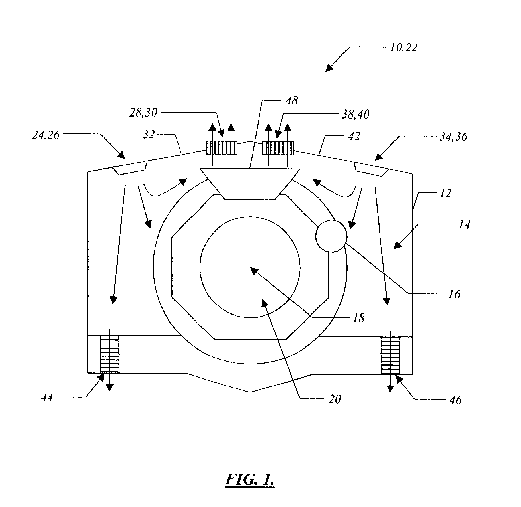
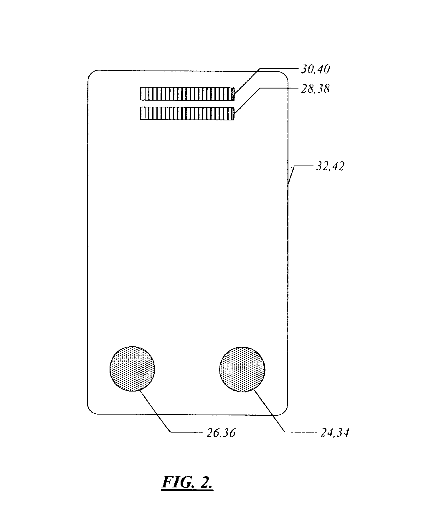
[0005]The computed tomography (“CT”) gantry cooling systems and methods of the present invention use a plurality of fans and vents disposed within the gantry covers of a CT system's gantry housing. These fans and vents are specifically configured and provide for the effective cooling of the CT gantry electronic and mechanical systems by pressurizing the gantry chamber, rather than evacuating it. This pressurization allows high-speed cooling air to be effectively directed at the rotating and / or stationary components disposed within the gantry chamber. Advantageously, a heat exchanger disposed within the gantry chamber is positioned proximal to several of the vents and exhausts air along a path that bypasses many of the temperature-sensitive CT gantry electronic and mechanical systems. Increased cooling efficiency means that relatively quiet fans may be used, minimizing overall CT system noise generation. The position of the fans and the pressurization of the gantry chamber prevent dust from accumulating within the gantry chamber and collecting on the sensitive components disposed therein.

Problems solved by technology

Computed tomography (“CT”) gantry electronic and mechanical systems, such as x-ray tubes, data acquisition system converter cards, power supplies, and the like, are relatively inefficient and generate a significant amount of heat during normal operation.
If the air disposed within the gantry chamber becomes too hot, the temperature of the one or more detectors may not be adequately controlled and overall CT system performance may suffer.
Alternatively, expensive air conditioning units and / or cooling software packages are used.
Such conventional CT systems and methods do little to provide for mixing of the air disposed within the gantry chamber, resulting in inadequate cooling of the gantry and its components.
Additionally, drawing air from the lower portion of the CT system, near the floor, and expelling it out of the upper portion of the gantry chamber, through the upper portion of the gantry housing, causes a significant amount of dust to accumulate within the gantry chamber and collect on the sensitive components disposed therein.

Method used


Image

  • Computed tomography gantry cooling systems and methods
  • Computed tomography gantry cooling systems and methods
  • Computed tomography gantry cooling systems and methods

Examples


Embodiment Construction

[0013]As described above, the computed tomography (“CT”) gantry cooling systems and methods of the present invention use a plurality of fans and vents disposed within the gantry covers of a CT system's gantry housing. These fans and vents are specifically configured and provide for the effective cooling of the CT gantry electronic and mechanical systems by pressurizing the gantry chamber, rather than evacuating it. This pressurization allows high-speed cooling air to be effectively directed at the rotating and / or stationary components disposed within the gantry chamber. Advantageously, a heat exchanger disposed within the gantry chamber is positioned proximal to several of the vents and exhausts air along a path that bypasses many of the temperature-sensitive CT gantry electronic and mechanical systems. Increased cooling efficiency means that relatively quiet fans may be used, minimizing overall CT system noise generation. The position of the fans and the pressurization of the gantr...


PUM


Abstract

A computed tomography (“CT”) gantry cooling system including a gantry housing defining a gantry chamber, wherein the gantry housing includes a lower portion, an upper portion, and a gantry cover disposed adjacent to the upper portion of the gantry housing. The CT gantry cooling system also including a fan disposed within the gantry cover of the gantry housing, wherein the fan is operable for forcing cooling air into the gantry chamber and creating a positive pressure within the gantry chamber. The CT gantry cooling system further including a vent disposed within the gantry cover of the gantry housing, wherein the vent is operable for exhausting heated air from the gantry chamber.

Description

FIELD OF THE INVENTION[0001]The present invention relates generally to computed tomography (“CT”) systems and methods. More specifically, the present invention relates to CT gantry cooling systems and methods.BACKGROUND OF THE INVENTION[0002]Computed tomography (“CT”) gantry electronic and mechanical systems, such as x-ray tubes, data acquisition system converter cards, power supplies, and the like, are relatively inefficient and generate a significant amount of heat during normal operation. Typically, this heat is trapped within a chamber, referred to herein as a gantry chamber, which is defined by a relatively large box-like structure or housing having a hole running through it. This housing is referred to as a gantry housing or, simply, a gantry. A moveable table engages the hole in the gantry and is operable for supporting and aligning a patient or the like in relation to the x-ray tube and the like. Other components disposed within the gantry chamber are relatively sensitive to...

Claims


Application Information

Patent Timeline
IPC IPC(8): A61B6/03H01J35/10H01J35/00H05G1/02H05G1/00G01N
CPCA61B6/4488A61B6/035
Inventor RAY, SHAWN A.KENDALL, CHARLES B.
Owner GENERAL ELECTRIC CO
Learn More