
Dual LED/incandescent security fixture

a security fixture and led light technology, applied in lighting and heating apparatus, light source combinations, instruments, etc., can solve the problem of much more energy consumption, and achieve the effect of increasing the illumination level of the area

Inactive Publication Date: 2005-06-21
RGT UNIV OF CALIFORNIA
View PDF8 Cites 134 Cited by
  • Summary
  • Abstract
  • Description
  • Claims
  • Application Information

AI Technical Summary

Benefits of technology

This hybrid system achieves energy savings, prolonged illumination, enhanced visibility, and aesthetic flexibility with colored LEDs, offering the best cost-effectiveness and security benefits by minimizing the number of LEDs and maximizing lumen output when needed.

Problems solved by technology

LEDs are not the ideal choice because white light is generally needed and only colored LEDs are generally available.
Incandescent lights can be used but consume much more energy.

Method used


Image

  • Dual LED/incandescent security fixture
  • Dual LED/incandescent security fixture
  • Dual LED/incandescent security fixture

Examples


Embodiment Construction

[0011]The invention may be Implemented in a number of different embodiments. The following are illustrative but not limiting.

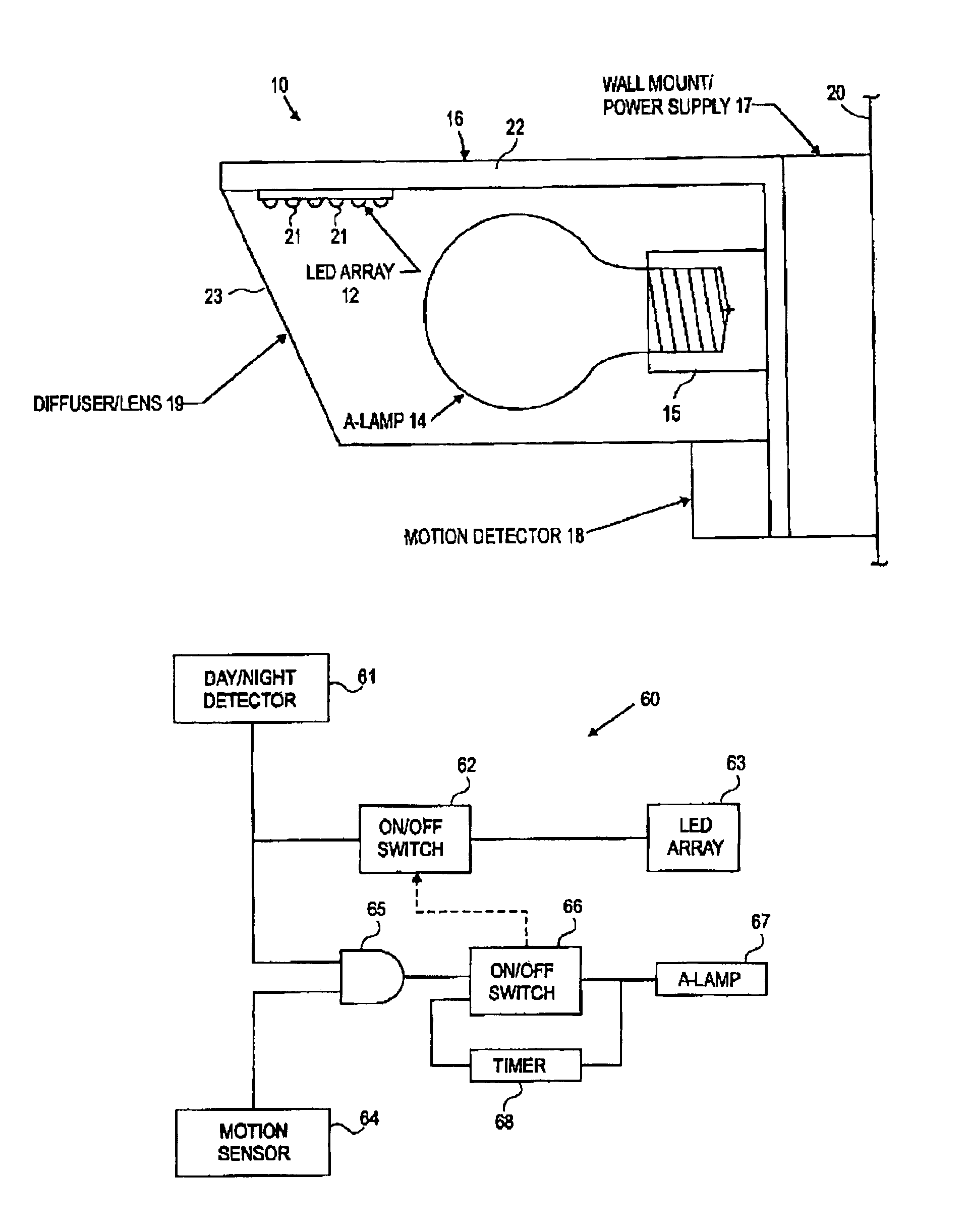
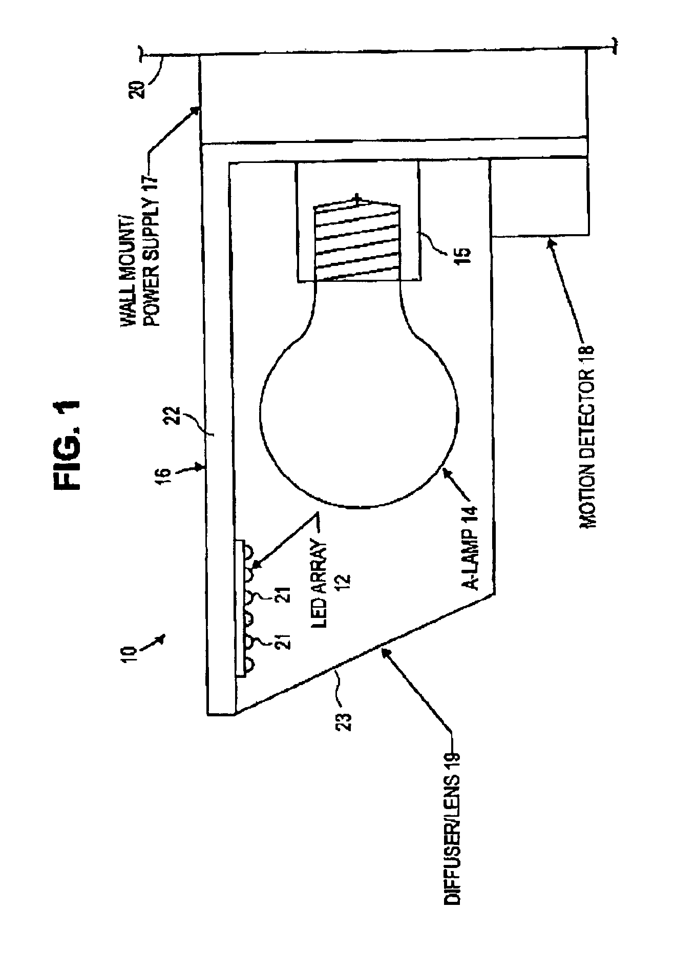
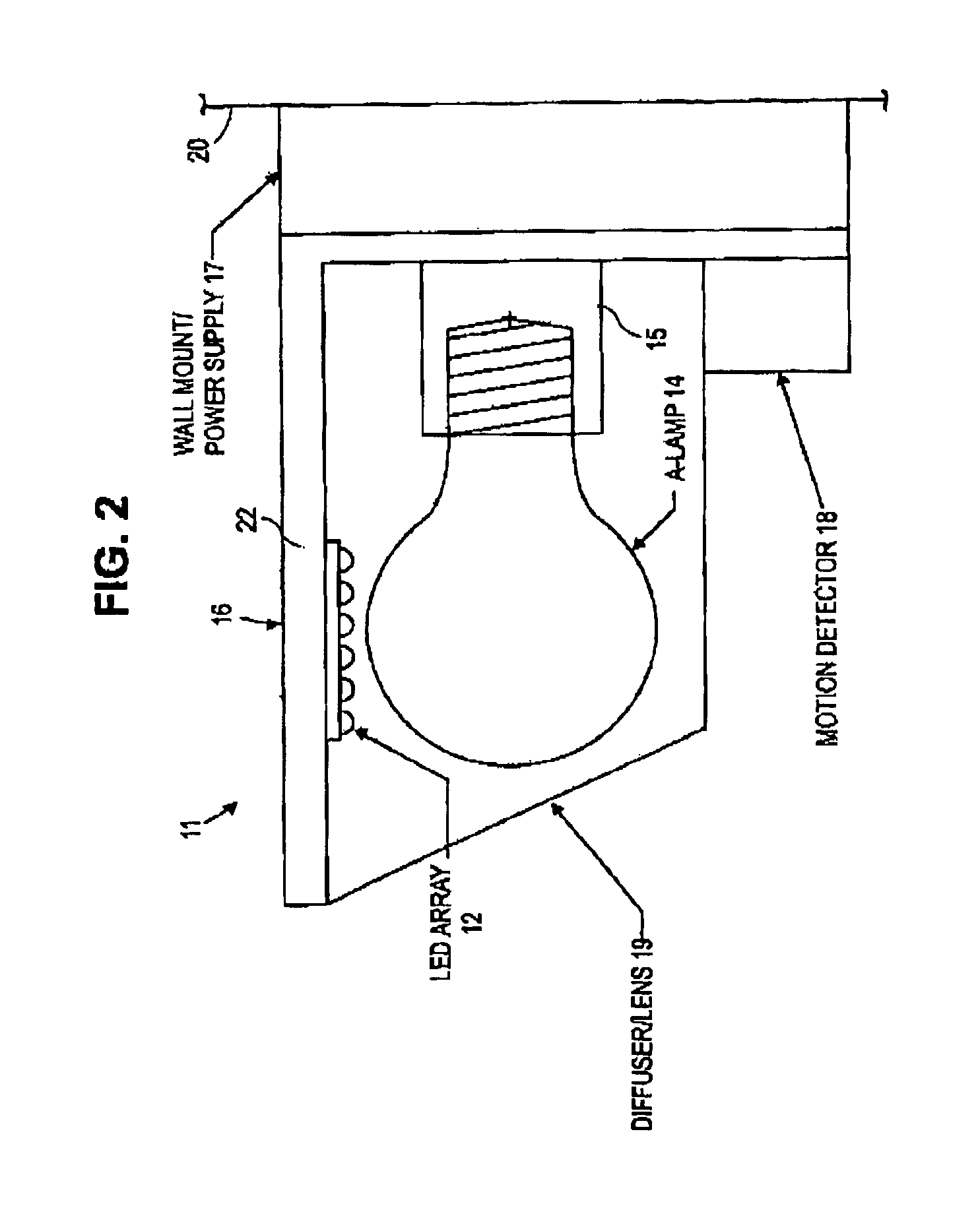
[0012]As shown in FIG. 1, hybrid LED / incandescent light fixture 10 combines an LED array 12 and an incandescent lamp (A-lamp) 14 in a single housing 16. The incandescent source or lamp 14 screws into a standard socket 15 and is held in a horizontal position. The LED array 12 is placed facing down from the top 22 of the housing 16, near the front edge, and extending forward substantially beyond A-lamp 14. The top 22 of housing 16 not only supports the LED array 12 but also provides a heatsink for the LED array 12 and provides a physical shield to prevent light from either the LED array 12 or A-lamp 14 from traveling upwards into the night sky. Housing 16 is attached to a wall mount / power supply unit 17, which is attached to wall 20 and electrically connected to a power source, typically standard electrical wiring from a power line. Socket 15 and LED array 12 ar...


PUM


Abstract

A dual LED and incandescent security lighting system uses a hybrid approach to LED illumination. It combines an ambient LED illuminator with a standard incandescent lamp on a motion control sensor. The LED illuminator will activate with the onset of darkness (daylight control) and typically remain on during the course of the night (“always on”). The LED illumination, typically amber, is sufficient to provide low to moderate level lighting coverage to the wall and ground area adjacent to and under the fixture. The incandescent lamp is integrated with a motion control circuit and sensor. When movement in the field of view is detected (after darkness), the incandescent lamp is switched on, providing an increased level of illumination to the area. Instead of an “always on” LED illuminator, the LEDs may also be switched off when the incandescent lamp is switched on.

Description

GOVERNMENT RIGHTS[0001]The United States Government has the rights in this invention pursuant to Contract No. DE-AC03-76SF00098 between the United States Department of Energy and the University of California.BACKGROUND OF THE INVENTION[0002]The invention relates generally to LED lighting systems and more particularly to security lighting systems with LEDs.[0003]As LED technology progresses, LEDs will be used for many lighting applications. White light LEDs are still in their infancy and questions regarding their color rendering and lifetime need to be resolved before wide scale commercial adoption. Colored LEDs, however, are a proven technology, and as outputs continue to increase, colored lighting opportunities will be further enabled. Exit signs and traffic signals are examples of colored lighting markets that have seen widespread commercial success by LEDs and soon may be dominated if not monopolized by LEDs.[0004]Security lighting, particularly in outdoor environments, is a ligh...

Claims


Application Information

Patent Timeline
Patent Type & Authority Patents(United States)
IPC IPC(8): H05B37/02F21S8/00F21V23/04
CPCF21K9/135F21K9/52F21S8/035F21V23/0442H05B37/0218H05B37/0227F21Y2105/001F21Y2113/02Y02B20/46F21Y2101/02F21Y2105/10F21K9/232F21K9/61F21Y2115/10F21Y2113/20H05B47/11Y02B20/40H05B47/115
Inventor GAUNA, KEVIN WAYNE
Owner RGT UNIV OF CALIFORNIA
Learn More