Cervical disc replacement

a cervical disc and intervertebral disc technology, applied in the field of cervical disc replacement implants, can solve the problems of significant pain to the individual suffering from the condition, undesirable progressive fusion of a long sequence of vertebrae, etc., and achieve the effect of immediate and short-term relief from pain

Inactive Publication Date: 2005-06-21
HOWMEDICA OSTEONICS CORP
View PDF17 Cites 229 Cited by
  • Summary
  • Abstract
  • Description
  • Claims
  • Application Information

AI Technical Summary

Benefits of technology

[0018]Finally, it is contemplated by the present invention that during axial rotation of the adjacent vertebral bones of the cervical segment relative to one another about the longitudinal axis of the spinal column, the opposing bones do not simply axially rotate relative to one another for more than a few degrees, but rather follow the coupled influences of the unco-vertebral joints and the nucleus, and that this coupled motion vertically separates the opposing bones of the facet joints as the rotation continues, thus freeing the bones to rotate farther that would otherwise be permitted if the facets locked together (as is often seen as a symptom of degenerative cervical disease).
[0019]Both the Bryan and Bristol discs described above do provide distraction and maintenance of intervertebral disc height, and thereby provide immediate and short-term relief from pain. However, it should be understood, in light of the above described anatomy as contemplated by the present invention, that neither provides for proper anatomical motion because their respective centers of rotation are located within the disc space. Thus, neither will afford significant motion preservation, and patients with these devices implanted in their necks will find no significant mobility at the implanted segment. This may lead to spontaneous fusions, long term facet deterioration, and / or accelerated adjacent level degeneration.
[0033]It is preferable that, in addition to the flexion, extension, and lateral bending motions described above, the adjacent vertebral bones be permitted by the artificial disc implant to axially rotate relative to one another (e.g., about the longitudinal axis of the spinal column), through a small range of angles, without moving in opposite (or otherwise directed away from one another) directions (e.g., along the longitudinal axis) within that range, and then to engage in such opposite (or otherwise directed away from one another) movement once that range is exceeded. Preferably, the articulation surfaces 204, 304 are accordingly configured and sized to permit such movements. In a preferred configuration, the constant radius of curvature A is larger than the constant radius of curvature C, and the constant radius of curvature D is larger than the constant radius of curvature B. Because of the space, afforded by the differing radii, at the edges of the articulation surfaces, the upper and lower elements are able to axially rotate relative to one another about the longitudinal axis of the spinal column through a range of angles without causing the vertebral body contact surfaces to move away from one another along the longitudinal axis. Once the axial rotation exceeds that range, the articulation surfaces interfere with one another as the concave arcs move toward positions in which they would be parallel to one another, and the distance between the vertebral body contact surfaces increases with continued axial rotation as the concave arcs ride up against their oppositely directed slopes. Thus, the articulation surfaces are configurable according to the present invention to permit normal physiologic axial rotational motion of the adjacent vertebral bones about the longitudinal axis through a range of angles without abnormal immediate axially opposite (or otherwise directed away from one another) movement, and to permit such axially opposite (or otherwise directed away from one another) movement when under normal physiologic conditions it should occur, that is, outside that range of angles.

Problems solved by technology

This degeneration of this critical disc material, from the hydrated, elastomeric material that supports the separation and flexibility of the vertebral bones, to a flattened and inflexible state, has profound effects on the mobility (instability and limited ranges of appropriate motion) of the segment, and can cause significant pain to the individual suffering from the condition.
Unfortunately, until the advent of spine arthroplasty devices, the only methods known to surgeons to maintain the necessary disc height necessitated the immobilization of the segment.
Either way, however, it is clear that a progressive fusion of a long sequence of vertebrae is undesirable from the perspective of the patient's quality of life as well as from the perspective of pushing a patient to undergo multiple operative procedures.

Method used


Image

  • Cervical disc replacement
  • Cervical disc replacement
  • Cervical disc replacement

Examples


Embodiment Construction

[0042]For the purposes of promoting an understanding of the principles of the invention, reference will now be made to the embodiment illustrated in the drawings and specific language will be used to describe the same. It will nevertheless be understood that no limitation of the scope of the invention is thereby intended, such alterations and further modifications in the illustrated device, and such further applications of the principles of the invention as illustrated therein, being contemplated as would normally occur to one skilled in the art to which the invention relates.

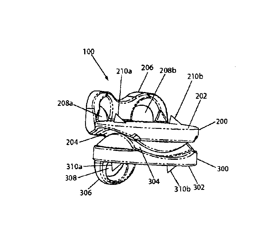
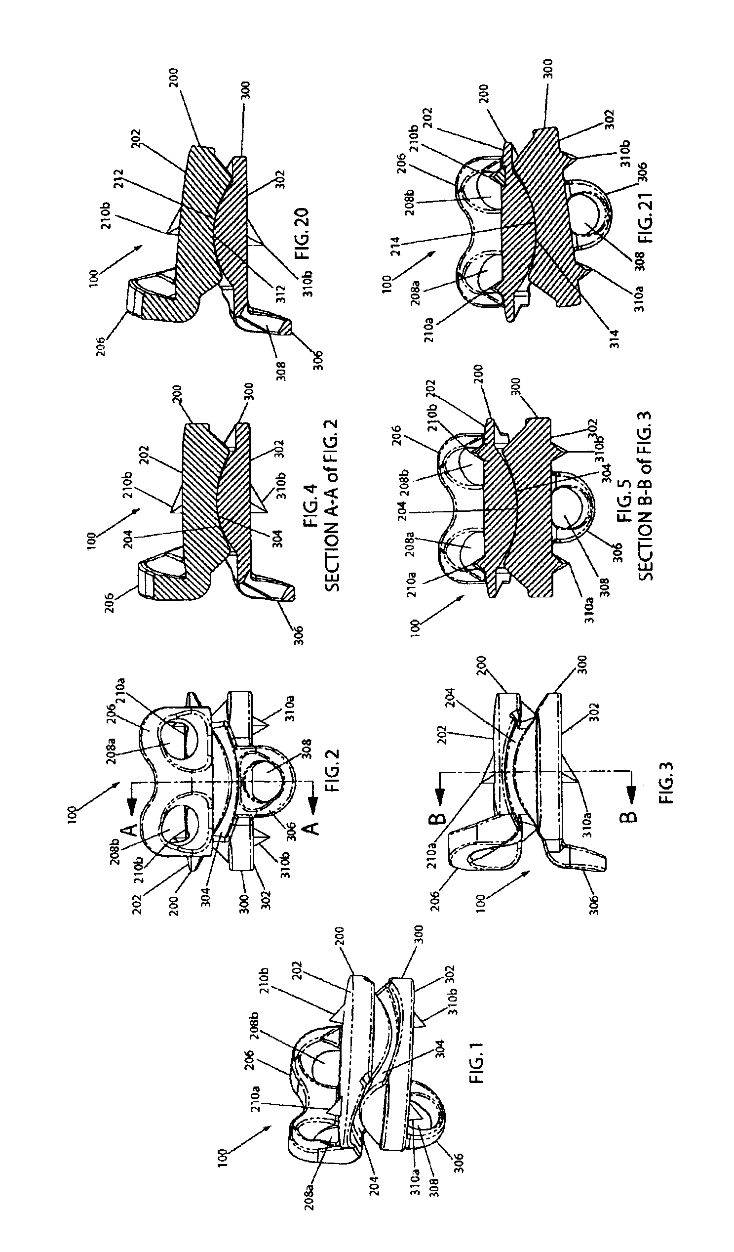
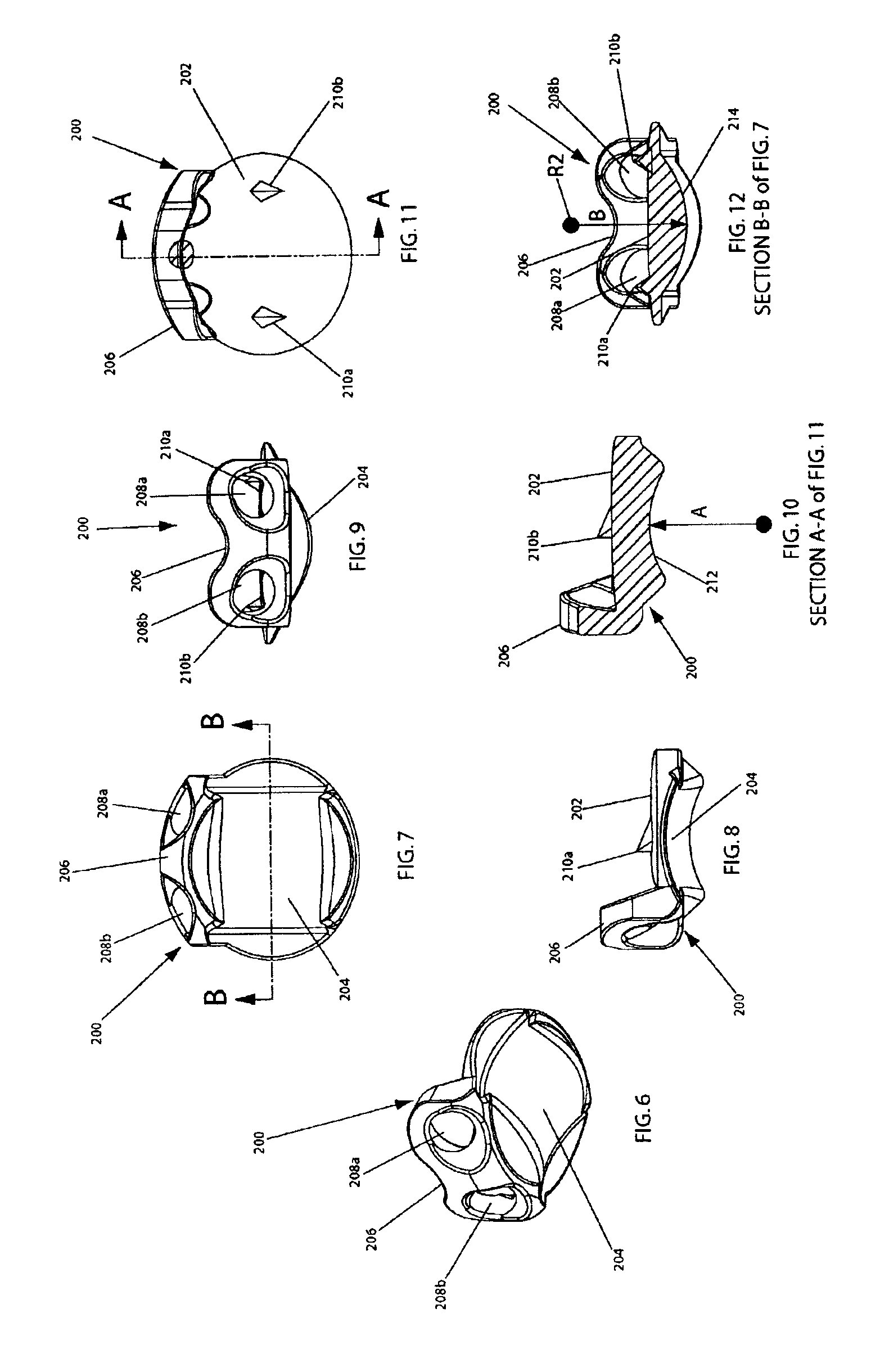
[0043]Referring now to FIGS. 1-5, an artificial disc implant 100 of the present invention is shown in perspective, anterior, lateral, lateral cutaway, and posterior cutaway views, respectively. The implant 100 includes a first (e.g., upper) element 200 and a second (e.g., lower) element 300, each having an outwardly facing vertebral body contact surface 202, 302, and each having an inwardly facing articulation ...


PUM


Abstract

An articulating joint implant for use in the cervical spine includes a pair of opposing upper and lower elements having nested articulation surfaces providing a center of rotation of the implant above the adjacent vertebral body endplate surfaces in one mode of motion lateral bending and a center of rotation of the implant below those surfaces in flexion / extension, and that further permit axial rotation of the opposing elements relative to one another about the longitudinal axis of the spinal column through a range of angles without causing them to move in opposing directions along the longitudinal axis within that range. In preferred embodiments, the articulation surfaces further cause such opposite movement of the opposing elements beyond that range.

Description

FIELD OF THE INVENTION[0001]The present invention is directed to a cervical joint replacement implant and more particularly to a cervical intervertebral disc prosthesis having opposing constant radii saddle shaped articulating surfaces.BACKGROUND OF THE INVENTION[0002]The structure of the intervertebral disc disposed between the cervical bones in the human spine comprises a peripheral fibrous shroud (the annulus) which circumscribes a spheroid of flexibly deformable material (the nucleus). The nucleus comprises a hydrophilic, elastomeric cartilaginous substance that cushions and supports the separation between the bones while also permitting articulation of the two vertebral bones relative to one another to the extent such articulation is allowed by the other soft tissue and bony structures surrounding the disc. The additional bony structures that define pathways of motion in various modes include the posterior joints (the facets) and the lateral intervertebral joints (the unco-vert...

Claims


Application Information

Patent Timeline
Patent Type & Authority Patents(United States)
IPC IPC(8): A61B17/68A61B17/80A61F2/44A61F2/46A61B17/17A61B17/16A61B17/70A61B17/88A61B17/86A61F2/00A61F2/30
CPCA61B17/8033A61B17/8042A61F2/4425A61F2/4611A61F2/4684A61B17/1728A61F2002/30843A61B17/8625A61B17/866A61F2002/30301A61F2002/30578A61F2002/30616A61F2002/3065A61F2002/30841A61F2002/449A61F2002/4627A61F2002/4628A61F2002/4629A61F2230/0095Y10S623/908Y10S623/911A61B17/7059A61F2230/0065A61F2/442A61F2002/4625
Inventor ZUBOK, RAFAILVALDEVIT, ANTONIODUDASIK, MICHAEL W.ERRICO, JOSEPH P.
Owner HOWMEDICA OSTEONICS CORP
Why Eureka
Try Eureka