
Device for conveying piece goods

Active Publication Date: 2005-06-21
INTERROLL HLDG
View PDF29 Cites 12 Cited by
  • Summary
  • Abstract
  • Description
  • Claims
  • Application Information

AI Technical Summary

Benefits of technology

[0012]Another advantage of the invention is that the driving belt does not have to be made endless at the point Of the joint, but that both ends can be clamped in on the clamping profiles so that these ends rest against each other in a butt-joined way. In the clamped-in condition, the clamping forces acting between the clamping jaws, which oppose each other, and can consequently ensure not only the connection between the individual conveying and sorting systems and the driving belt. These clamping forces can also be used for creating an inexpensive, a particularly simple connection of the ends of the driving belt to form an endless belt. Thus, it is possible to obtain a particularly flexible application of all kinds of different constructions.
[0013]The driving belt, and consequently also the conveying device and the conveying and sorting systems, are usefully driven with the help of a friction wheel drive that is preferably realized in the form of the type of the proportional drive that is already known from DE 42 44 170 C2 incorporated herein by reference.
[0014]In another variation of the second alternative of the solution, the driving belt can be formed as a flat, flexible belt which, is reinforced with a tensile element of high strength that is extended all around in the area where its edge is clamped in a fixed manner by the clamping jaws of the respective clamping profile. Accordingly, in another beneficial embodiment of the first alternative of the solution, the driving belts are each reinforced with a tensile element of high strength that extends all around or all through. A steel cable comprised of stranded steel wire can preferably be used in each case for this purpose. On the other hand, the belt surrounding the tensile element, as in the case where no such reinforcement is used, preferably consists of a plurality of layers of fabric, for example of a polyester fabric. These layers comprise intermediate and cover layers as well. The layers, which point away from each other and form the external surface of the driving belt, preferably consist of polyurethane. Such a driving belt is flexible like the shafts for a horse. The above measures permit particularly favorable clamping conditions to be obtained and even more flexible movements in the vertical direction. The length of the belt corresponds with the overall length of the conveying line.
[0015]Another beneficial feature of both alternatives of the solution, provides that the clamping profiles can be formed as long-stretching clamping bars that extend in parallel with the driving belt. The clamping jaws of these clamping bars extend substantially over the total length of the clamping bars. Thus, in the clamped, fixed condition, the clamping jaws solidly abut or clamp substantially over the entire length of the clamping bars. This, in turn, means that further enhanced conveying and driving conditions are achieved, and that the maintenance intervals are also prolonged.
[0016]In another beneficial variation of both alternatives of the solution, the conveying systems can be formed as traveling carriages equipped with running rollers that are guided on a preferably central guide rail of the conveying line, which is arranged in the area of the transverse center of the respective conveying and sorting system, and which extends in the direction of conveyance. It is thus possible to always achieve constantly good guiding conditions, combined with favorable construction possibilities and low manufacturing tolerances, also when confronted with difficult conditions of curves, and even with conveying lines that intersect each other. Furthermore, it is possible by means of the measures specified above, to adjust in a simple manner a slanted position or inclination of the conveying system that is flexibly adapted to the application and user requirements, if necessary jointly with the sorting system, to be able to compensate for the centrifugal forces occurring when traveling through curved sections of the conveying line.
[0017]The traveling carriage can be is guided via at least three running rollers that are arranged at an angle of preferably 120 degrees around the longitudinal axis of the guide rail. This permits particularly favorable guiding and conveying conditions, along with a low-noise and low-maintenance operation over a long period of time. The running rollers can be formed as an arrangement gripping (or extending) around the guide rail, so that it is possible to support both the weight of the traveling carriage and to obtain support for the traveling carriage versus the force of gravity. This permits safe guidance and conveyance of the traveling carriages, if need be also when the traveling carriages are in a position that is inclined versus the horizontal line. This design makes the device able to satisfy the requirements to be met with respect to difficult conditions in curves in particular in the presence of elevated conveyance capacities.

Problems solved by technology

This construction is expensive and leads to increased wear, and a comparatively high level of noise.
For this reason, this construction has found no application in practical life.

Method used


Image

  • Device for conveying piece goods
  • Device for conveying piece goods
  • Device for conveying piece goods

Examples


Embodiment Construction

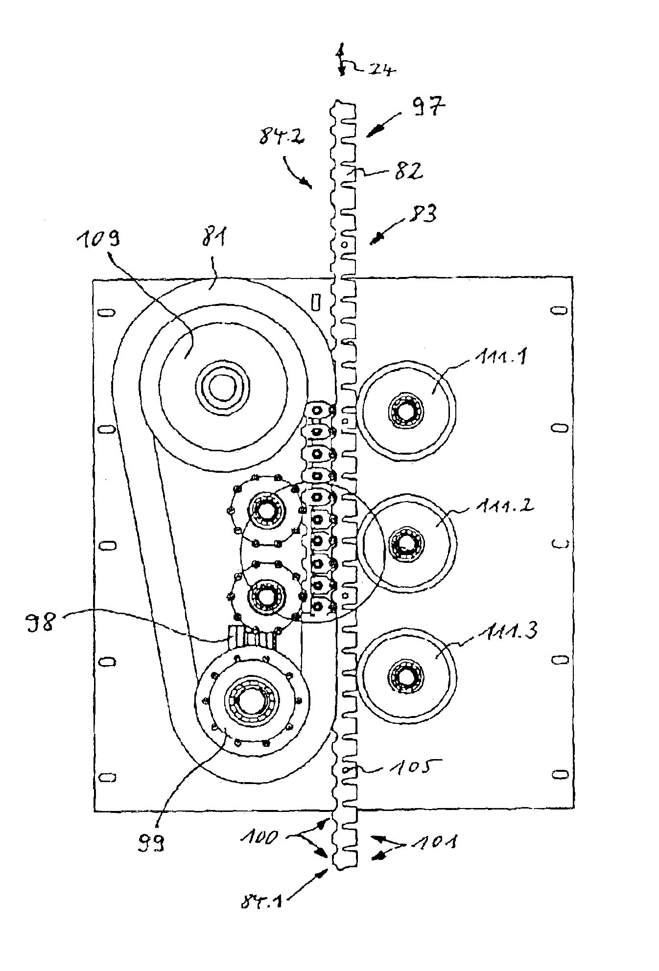
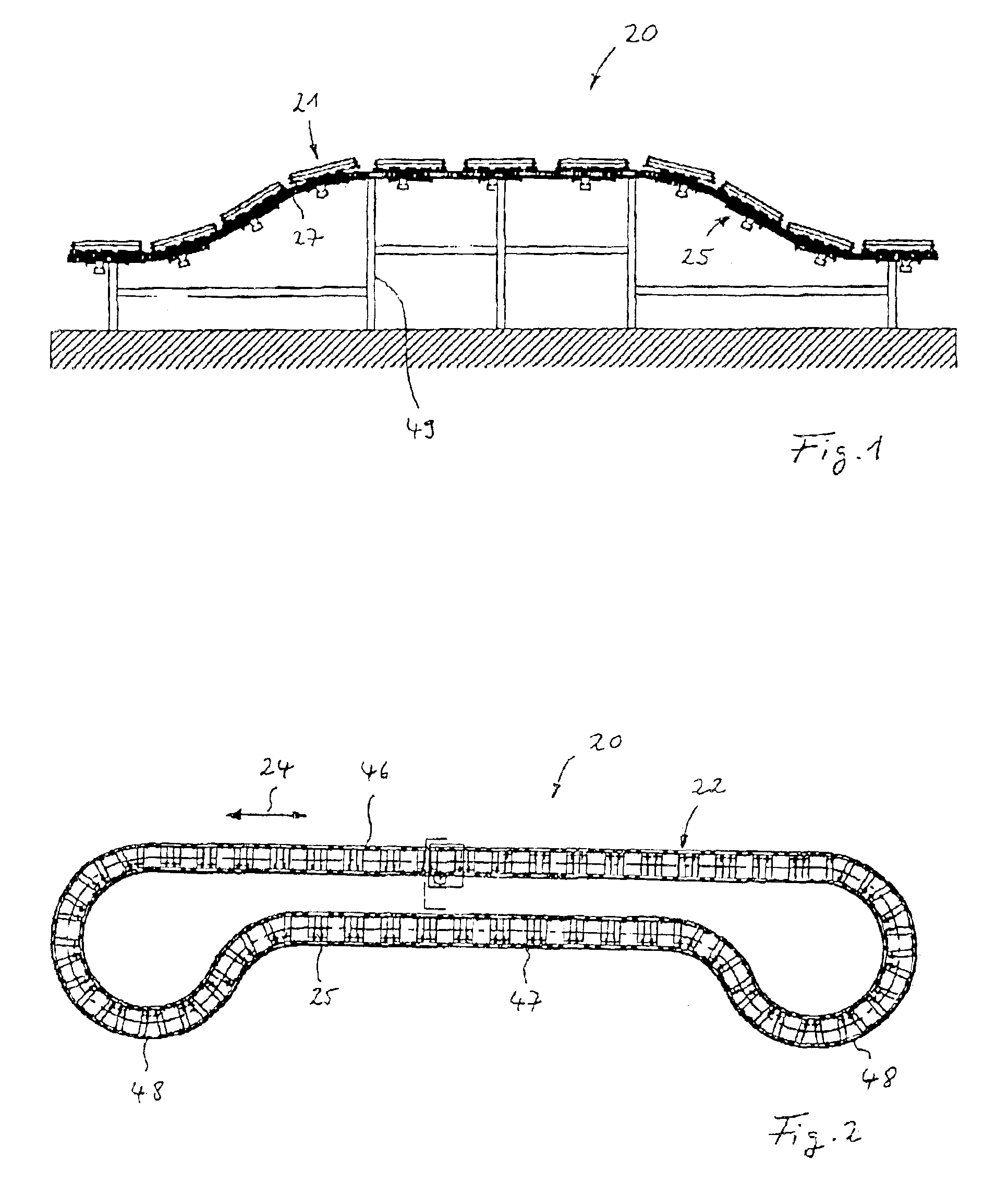
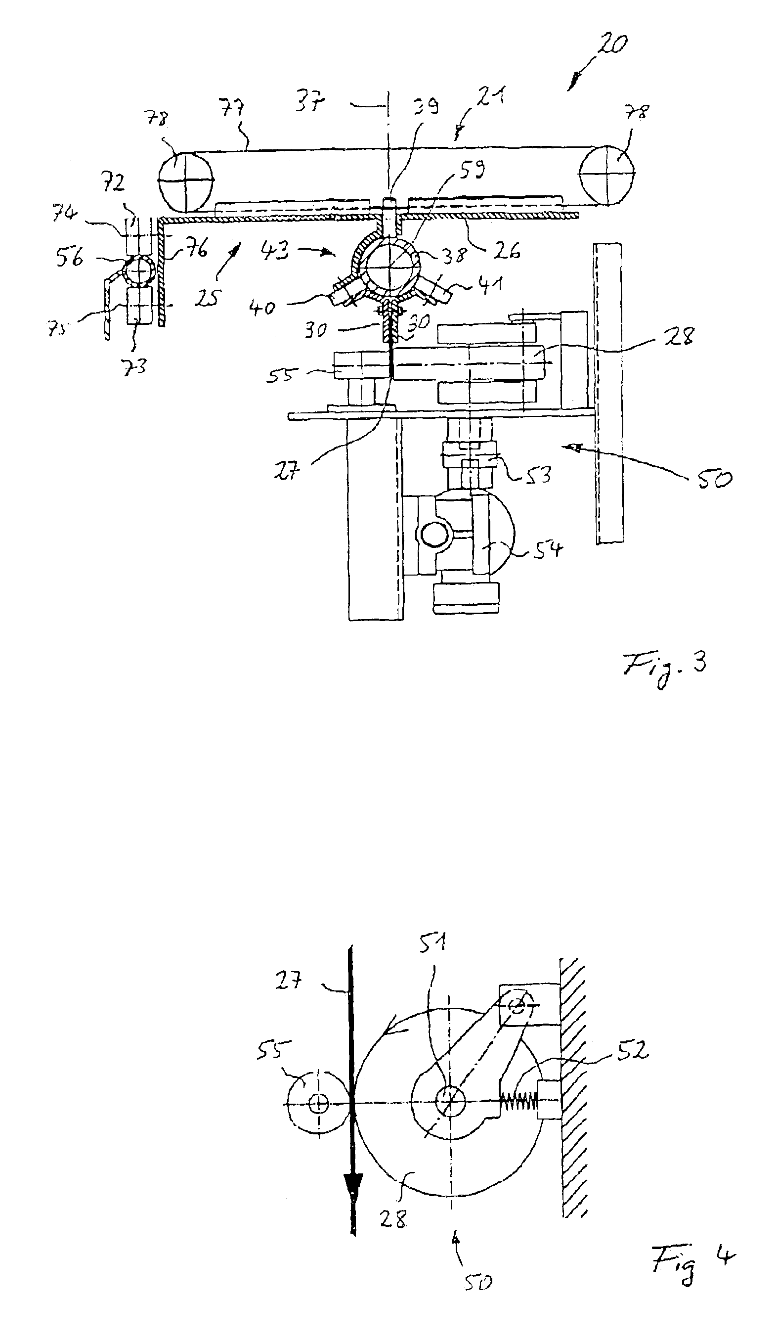
[0042]Referring in detail to the drawings, FIG. 1, FIG. 2 and FIG. 3 show device 20, which serves for conveying piece goods and, in the present case, is comprised of a sorting system 21 for distributing out or sorting the pieced goods in a targeted manner. With this design, the successively arranged conveying systems 25 in the form of traveling carriages 26 (SEE FIG. 3) and are guided along a conveying line 22 (FIG. 2), which, in the present case, forms a sorting line as well. Sorting systems 21 are secured on traveling carriages 26 and each comprise a rubber belt 77 (FIG. 3) that can be driven transversely in relation to conveying line 22 or transversely to the sorting line. Rubber belt 77 is guided in each case via a set of reversing rollers 78, with axles of rotation that extends in conveying direction 24. The transverse drive of rubber belts 77 of sorting systems 21 occurs by using a driving means that can be selectively caused to cooperate. These driving means are not shown in ...


PUM


Abstract

A device for conveying piece goods. The device comprises a sorting system for sorting the piece goods. The successively arranged conveying systems are guided with this device along a conveying line and can be driven by at least one driving means that engages a driving belt. In a first embodiment, there is a driving belt on the driving side and a driving belt on the driven side which each comprise a rubber chain comprising a toothed profile. The toothed profiles of both rubber chains are in a substantially similar form. The device can also have a driving belt that is clamped in a fixed manner between the clamping jaws of the rigid clamping profiles. These clamping jaws extend at least substantially over the entire length of respective conveying system or sorting system. Furthermore, the non-clamped length of driving belt between the successively disposed conveying systems is much shorter than the length of the clamping profiles.

Description

CROSS REFERENCE TO RELATED APPLICATIONS[0001]Applicant claims priority under 35 U.S.C. §119 of Jun. 22, 2002 Application No. DE 102 27 998.5-22 filed Jun. 22, 2002.BACKGROUND OF THE INVENTION[0002]The invention relates to a device for conveying piece goods, in particular to a device for conveying and sorting piece goods. In connection with this device, successively installed conveying and sorting systems are arranged along a conveying and sorting line and can be driven by at least one driving means that revolves along the conveying and sorting line. This revolving driving means is secured on the conveying systems and engages a driving belt that is secured on the conveying systems.[0003]A large number of conveying devices which are equipped both with and without sorting systems are known. These conveying devices often form a revolving, endless system. Predominantly, chains or V-belts serving as the tensile and supporting elements are used in this design serving as the endless conveyi...

Claims


Application Information

Patent Timeline
IPC IPC(8): B65G17/32B65G23/00B65G17/34B65G17/12B65G23/16
CPCB65G17/12B65G23/16B65G17/345B65G2207/18
Inventor AXMANN, NORBERT
Owner INTERROLL HLDG
Learn More