
Fault notification method and related provider facility

a provider facility and fault notification technology, applied in the field of provider systems, can solve problems such as service failure, system administrators' use of this method, and inability to prompt notification

Inactive Publication Date: 2005-06-14
NTT DOCOMO INC +1
View PDF13 Cites 58 Cited by
  • Summary
  • Abstract
  • Description
  • Claims
  • Application Information

AI Technical Summary

Benefits of technology

[0036]The method of the present invention enables a provider facility to specify at least a service type that is out of service according to a predetermined rule base and based on fault information of each device and to generate notification message data by entering the specified service type in a template data. The generated notification message data are automatically posted on a web site, thereby enabling the immediate provision of accurate fault information to users.

Problems solved by technology

In the event that a fault occurs in the system of a provider of an internet-based service providing such services, a system administrator is required to post notification of the fault and consequent service failure on a web page for the information of users.
However, use of this method places a great burden on system administrators.
However, it will be appreciated from the preceding description that, in the conventional art, prompt notification is not possible.
A further problem of the conventional art is that it is not possible to provide reliable information to end users about a projected restoration time of a failed service.
From this description, it will be apparent that in the conventional art end users of services are subject to undesirable delays in obtaining information about a service failure.
Further, they are unable to obtain reliable information about a projected time when a service will once more become available.

Method used


Image

  • Fault notification method and related provider facility
  • Fault notification method and related provider facility
  • Fault notification method and related provider facility

Examples


Embodiment Construction

[0044]One embodiment of the present invention will now be explained in detail with reference to the drawings.

1. Configuration of Communication Service System

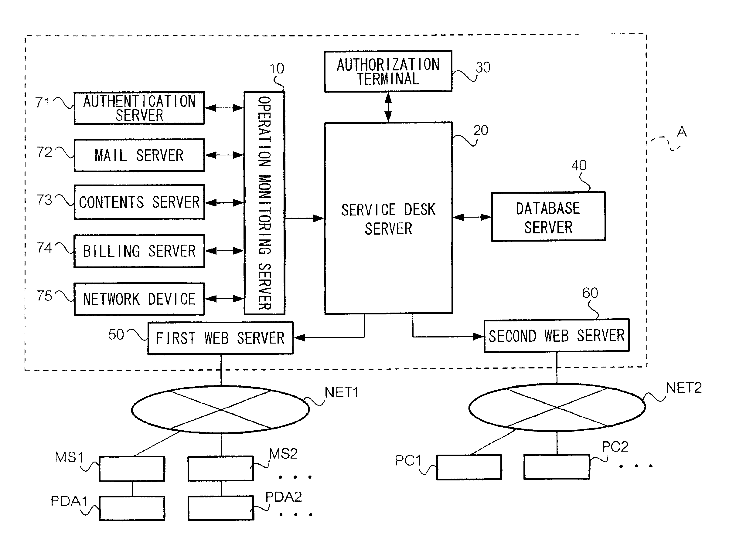
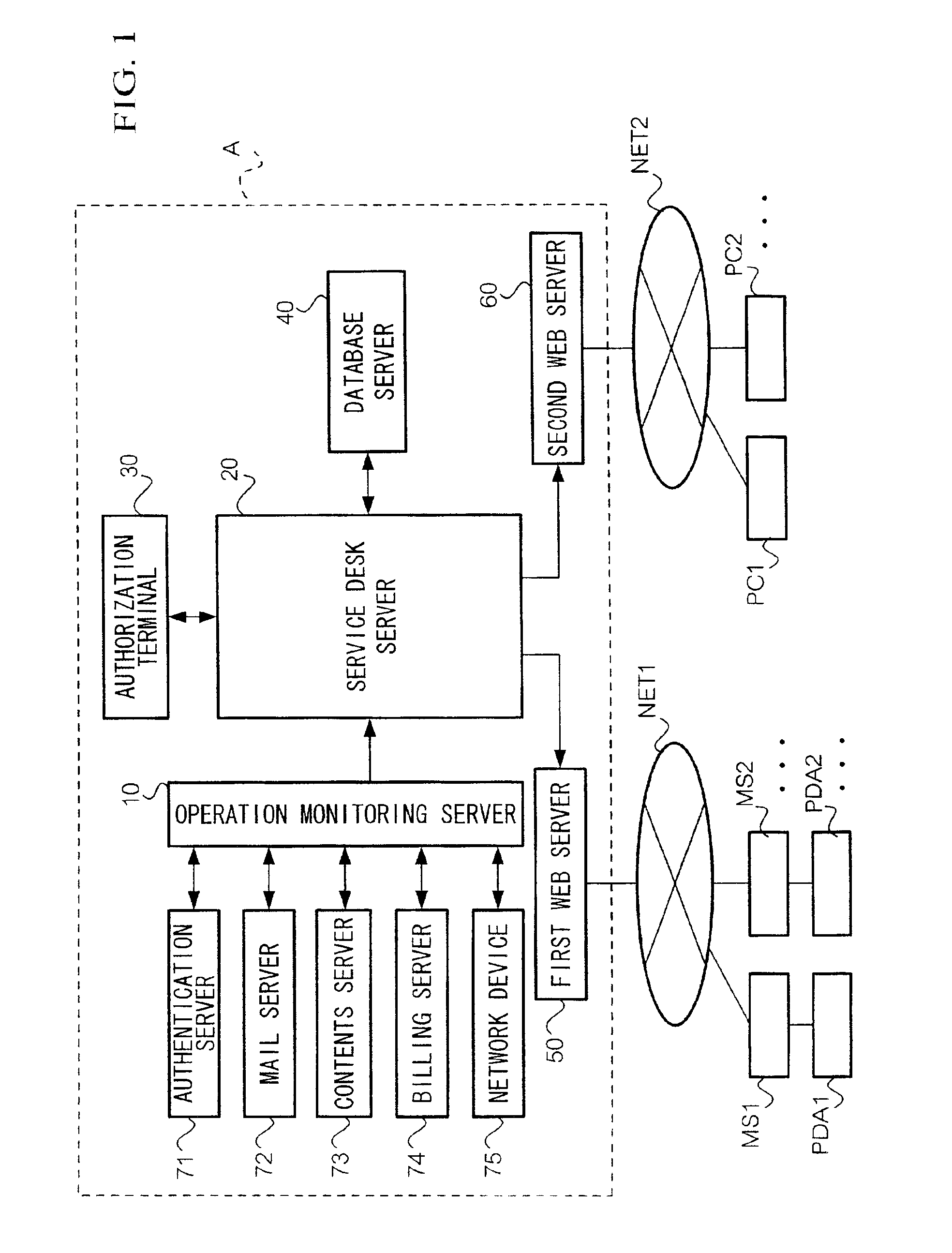
[0045]FIG. 1 is a block diagram illustrating a main configuration of a communication service system. As shown in the figure, a communication service system comprises a provider facility A, a first communication network NET1, a second communication network NET2, communication terminals MS1, MS2, . . . , personal computers PC1, PC2, . . . .

[0046]First communication network NET1 may be, for example, a radio communication network. Each communication terminal MS1, MS2, . . . may be, for example, a portable telephone, and a portable terminal PDA1, PDA2, . . . is connected thereto; each portable terminal having a small screen for display. A web browser is loaded in portable terminals PDA1, PDA2 and the Internet can be accessed via communication terminals MS1, MS2, . . . Alternatively, communication terminals MS1, MS2, . . . may be load...


PUM


Abstract

A service desk server receives trouble ticket information TC showing a fault status of a device, whereupon incident information X is generated (t0). Subsequently, the faulty service name is retrieved from fault information table based on the trouble ticket information TC. The service desk server then enters the service name in a template to generate fault notification message data html1 and html2 for transfer to a first and a second web server, respectively. Each of first and second web servers is thereby prompted to post a fault notification on their web site, on the basis of fault notification message data html1 and html2. Thus, fault information can be automatically notified to end users.

Description

BACKGROUND OF THE INVENTION[0001]1. Field of Invention[0002]The present invention relates to a provider system for providing a variety of services via a communication network to a terminal connected to the network, and to a fault notification method for posting on a web page notification of failure of a service due to a fault.[0003]2. Description of the Related Art[0004]The Internet has seen exponential growth in recent years, and many people using personal computers at home now have provider connectivity for browsing web sites and exchanging e-mail. In addition to PCs, people are increasingly utilizing portable telephones and terminals attached to portable phones, such as PDAs, to access the Internet and exchange mail. The use of services provided through a communication network such as the Internet is becoming increasingly common in peoples' daily lives.[0005]In the event that a fault occurs in the system of a provider of an internet-based service providing such services, a system...

Claims


Application Information

Patent Timeline
IPC IPC(8): G06F11/32H04L12/24G06F11/34G06F13/00
CPCG06F11/327H04L41/06H04L41/5054H04L41/5061H04L41/5074H04L41/5032G06F2201/875H04L41/5093
Inventor KATAGIRI, TOMOAKIKUBOTA, HIROSHI
Owner NTT DOCOMO INC
Learn More