
Multi-axial uterine artery identification, characterization, and occlusion pivoting devices and methods

Inactive Publication Date: 2005-06-14
VASCULAR CONTROL SYST
View PDF84 Cites 93 Cited by
  • Summary
  • Abstract
  • Description
  • Claims
  • Application Information

AI Technical Summary

Benefits of technology

[0014]According to a first aspect of the invention, a device useful for compressing a uterine artery of a patient comprises a handle having a proximal

Problems solved by technology

The devices and methods described in Burbank '601 have been useful in occluding a uterine artery; there have been some difficulties involved with their use.
Specifically, the aligned orientations of the imaging device, e.g., Doppler ultrasound device, and the element which passes through the tissue of the patient to occlude the uterine artery can be, for some patients and for some procedures, difficult to maintain.
Additionally, the devices and methods described in the '601 patent do not necessarily take advantage of the structure and symmetry of the female human anatomy to facilitate occlusion of a uterine artery.
The devices and methods of the '601 patent also are not well adapted for performing blood flow studies of a uterine artery.
As will be readily appreciated by those of skill in the art, prior devices are therefore difficult to use successfully.
As discussed above, the trouble is in identification of the artery and, once identified, maintaining a good position for obtaining the desired data is difficult.
No device which is currently commercially available can be used to simultaneously identify and occlude a uterine artery.
This high skill requirement has limited the use of surgical ligation of the uterine arteries as a clinical alternative for treatment of uterine fibroids and other uterine disorders.
Such devices are not well suited for use in measuring and / or monitoring the blood flow in a uterine artery.
While Bateman reported some success, this procedure involves opening the abdominal cavity, with the known attendant risks and disadvantages.

Method used


Image

  • Multi-axial uterine artery identification, characterization, and occlusion pivoting devices and methods
  • Multi-axial uterine artery identification, characterization, and occlusion pivoting devices and methods
  • Multi-axial uterine artery identification, characterization, and occlusion pivoting devices and methods

Examples


Embodiment Construction

[0028]Referring to the drawing figures, like reference numerals designate identical or corresponding elements throughout the several figures.

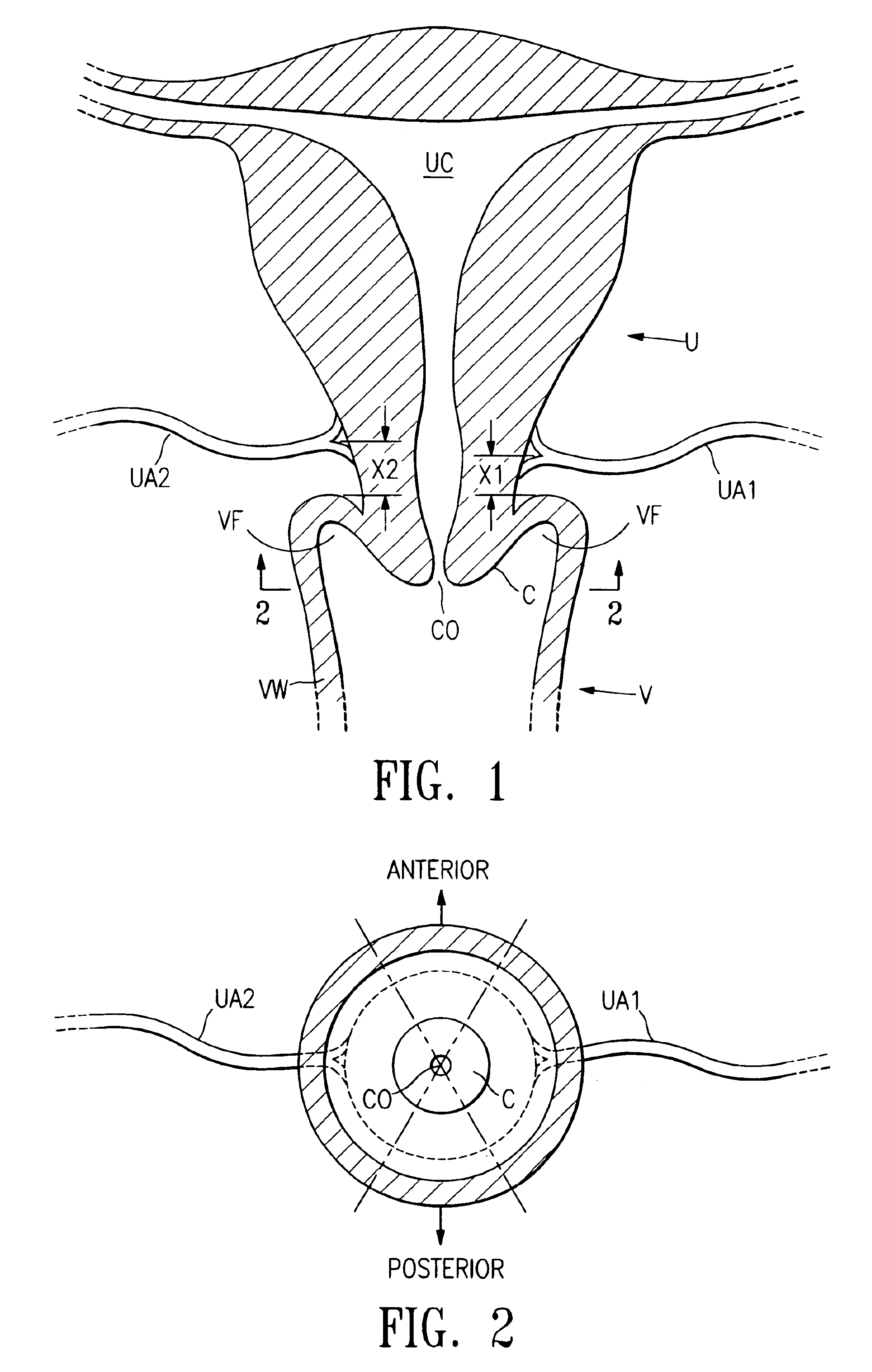
[0029]The inventors herein have discovered that the uterine arteries of female humans typically are about 3 cm or less from the vaginal wall at the vaginal fornix where the uterine artery meets the uterus, although the uterine arteries for a single patient sometimes are spaced at slightly different distances (see distances X1 and X2 in FIG. 1). The inventors herein have also discovered that the right uterine artery is typically positioned between about the 1 and 5 o'clock (see FIG. 2) positions, and more frequently between about 2 and 4 o'clock; and that there is typically symmetry between the uterine arteries, i.e., that the left uterine artery is typically positioned between about the 7 and 11 o'clock positions, and more frequently between about 8 and 10 o'clock. The inventors herein have also discovered that the cervix can be used as a platf...


PUM


Abstract

A system is provided for compressing one or both of the uterine arteries of a patient which is at least in part shaped to complement the shape of the exterior of the cervix, which allows the system to be self-positioning. One or more Doppler chips can be mounted or incorporated into the system which permit the practitioner to better identify the uterine artery and monitor blood flow therein. The system includes a pair of pivotally joined elements which can be moved toward and away from the cervix to compress a uterine artery.

Description

[0001]This application is related and claims priority under 35 U.S.C. § 119 to U.S. provisional patent application Ser. No. 60 / 279,477, filed Mar. 28, 2001, the entire contents of which are incorporated by reference herein. This application is also related to an application filed on even date herewith entitled “Multi-axial uterine artery identification, characterization, and occlusion devices and methods”, by Fred Burbank, Grieg E. Altieri, and Michael L. Jones, the entire contents of which are incorporated by reference herein.BACKGROUND OF THE INVENTION[0002]1. Field of the Invention[0003]The present invention relates to devices, systems, and processes useful for compressing a uterine artery, and more particularly to devices and systems capable of easily locating, compressing, and / or monitoring or characterizing the blood flow through a uterine artery.[0004]2. Brief Description of the Related Art[0005]It has been proposed that occlusion of the uterine arteries of a human female pat...

Claims


Application Information

Patent Timeline
IPC IPC(8): A61B17/122A61B17/12A61B17/128A61B8/06A61B17/42A61B5/026A61B17/00A61B18/00A61M25/00
CPCA61B5/415A61B5/418A61B8/06A61B8/12A61B17/122A61B17/1285A61B17/2812A61B17/12A61B5/026A61B17/00234A61B2017/4216A61B17/128A61B17/42A61B2017/0046
Inventor BURBANK, FRED H.ALTIERI, GREIG E.JONES, MICHAEL L.
Owner VASCULAR CONTROL SYST
Learn More