
Sheet feeder avoiding sheet sag

a feeder and sheet technology, applied in the field of feeding sheets, can solve the problems of uneven frictional drag, sheet may not feed evenly, and jamming of sheets within the printer, so as to improve beam strength and prevent sag and function

Inactive Publication Date: 2005-06-07
BRADY JOHN A +1
View PDF15 Cites 22 Cited by
  • Summary
  • Abstract
  • Description
  • Claims
  • Application Information

AI Technical Summary

Benefits of technology

This invention provides a sheet guide at the wall of an imaging device that causes the sheet to bend along the direction of insertion and prevents sagging. The guide structures are intuitive and easy to operate, and they force the sheet to bend without causing any damage to the image device. The bent sheet has increased beam strength, which is important for accurate imaging. The invention can be implemented with a single bend or multiple, parallel bends.

Problems solved by technology

Reliably positioning the sheet is important because, if the sheet sags against the imaging device structure, the sheet may not feed evenly.
When the sheet sags against the device an uneven frictional drag can occur and the sheet enters the sheet feed mechanism turned from the intended position.
In extreme cases the sheet jams within the printer.
Experience indicates that defective insertions will occur fairly frequently, especially with new operators.
However, such guide surfaces necessarily extend from the side of the imaging device during use.
Such operator intervention reduces productivity and requires some training of the operator.
The tray structures themselves add cost to the imaging device, and, since they are thin and relatively unprotected, they are subject to damage.

Method used


Image

  • Sheet feeder avoiding sheet sag
  • Sheet feeder avoiding sheet sag
  • Sheet feeder avoiding sheet sag

Examples


Embodiment Construction

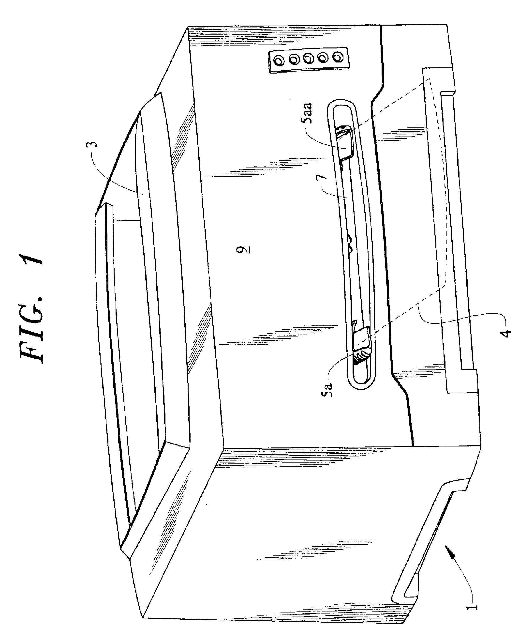
[0014]The printer 1 in FIG. 1 is shown without details as it is intended to be illustrative since this invention would be operable with virtually any imaging device. The imaging engine of printer 1 (internal and not shown) might be a conventional xerographic system. Printer 1 has an internal paper tray to supply paper from a stack of paper without manual intervention except to refill the tray. The imaged paper or other sheet is exited onto the top surface or tray 3 of printer 1. A sheet of paper 4 inserted in accordance with this invention is shown, in dotted outline for overall clarity of FIG. 1.

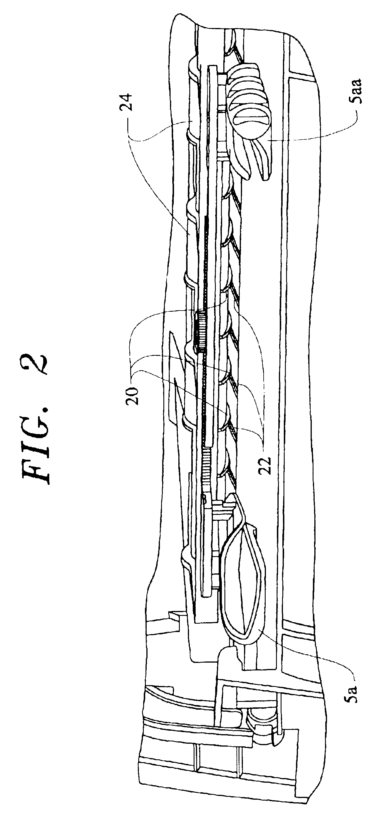
[0015]The paper 4 has a bowed configuration along the direction of entry, which is required by the left, and right guide structures, 5a and 5aa respectively. The center of paper 4 is at or near the bottom of slot 7, while the configuration of guide structures 5a and 5aa lift the left and right sides of paper 4 above the bottom of slot 7.

[0016]Slot 7 is an opening in the front side 9 of prin...


PUM

PropertyMeasurementUnit
sheet feedaaaaaaaaaa
widthaaaaaaaaaa
heightaaaaaaaaaa

Abstract

An entrance guide for externally fed sheet (4) to printer (1) is configured to bow the sheets. In one embodiment guides (5a, 5aa) within slot 7 have upper and lower configurations which force sheet into a bow. In one embodiment slot (7a) is bowed and is sufficiently narrow in height to only accept a bowed sheet. The bowed sheets do not sag against the printer (1), which aids in sheet registration.

Description

TECHNICAL FIELD[0001]This invention is to feeding sheets in a manner, which causes the sheets to be accurately received in transport mechanism so as to be properly positioned for imaging. Typically the sheets are intended to be manually inserted in the imaging device.BACKGROUND OF THE INVENTION[0002]In imaging devices, such as printers, feeding sheets individually from external of the imaging device allows selection of individual sheets having unique characteristics, such as letterhead or preprinted borders, or selected width. It is common to either simply provide a slot leading to the sheet transport mechanism of the device or to provide an external tray on which the sheet is slid across so as to be more reliably positioned in the sheet transport.[0003]Reliably positioning the sheet is important because, if the sheet sags against the imaging device structure, the sheet may not feed evenly. When the sheet sags against the device an uneven frictional drag can occur and the sheet ente...

Claims


Application Information

Patent Timeline
Patent Type & Authority Patents(United States)
IPC IPC(8): B65H5/38
CPCB65H5/38B65H2301/51214B65H2404/742B65H2407/21B65H2511/12B65H2220/01B65H2220/04
Inventor GORDON, MICHAEL KURTWADE, THOMAS CAMPBELL
Owner BRADY JOHN A
Learn More