Eureka AIR delivers breakthrough ideas for toughest innovation challenges, trusted by R&D personnel around the world.

Percussion electrical hand-held tool

Inactive Publication Date: 2005-06-07
HILTI AG
View PDF15 Cites 28 Cited by
  • Summary
  • Abstract
  • Description
  • Claims
  • Application Information

AI Technical Summary

Benefits of technology

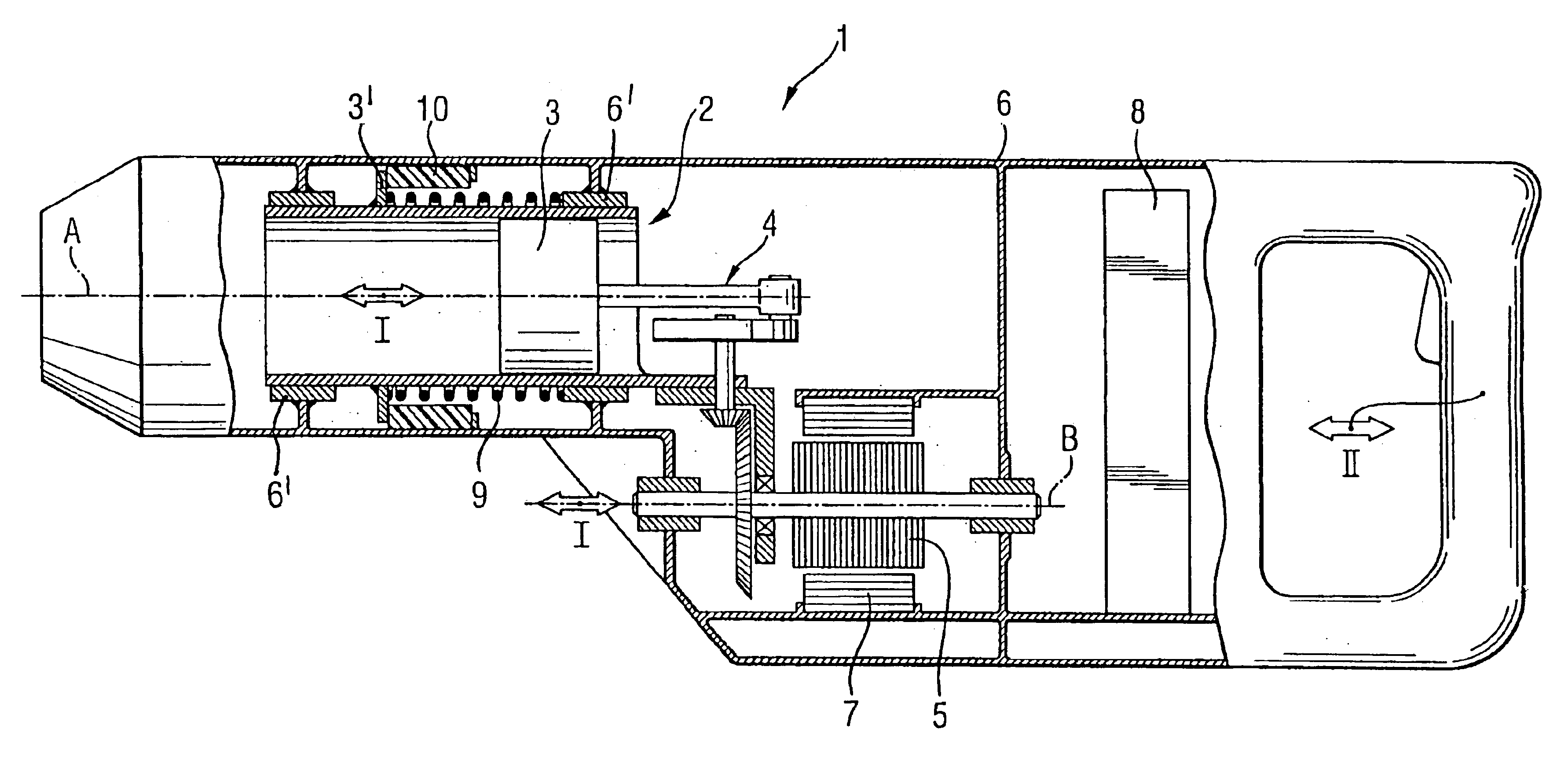
[0014]The mass ratio of the two subassemblies is shifted toward the first subassembly so that, finally, the two subassemblies have substantially the same mass. As a result, the damping element, which is provided between the two subassemblies, can dissipate more recoil energy, which reduces the oscillation amplitude of the second subassembly that includes the housing.
[0016]The driving chain for generating the percussions and / or rotational movement of the electrical hand-held tool has substantially wear-free coupling means which provide for the relative movement. The coupling means is formed as a torque spanner coupling, with a magnetic rotary field of the stator acting on the axially displaceable, brushless rotor. In particular, mechanical force-transmitting and, therefore, wear-susceptible coupling for compensation of the relative movement between the two subassemblies becomes unnecessary. With the use of the collectorless rotor, the collectors, which are susceptible to wear during the axial movement, are also eliminated.

Problems solved by technology

As a result, the damping element, which is provided between the two subassemblies, can dissipate more recoil energy, which reduces the oscillation amplitude of the second subassembly that includes the housing.

Method used


Image

  • Percussion electrical hand-held tool
  • Percussion electrical hand-held tool

Examples


Embodiment Construction

[0019]A percussion, electrical hand-held tool 1 according to the present invention, which is shown in the drawing, includes a first subassembly with a percussion mechanism 2. The first subassembly is supported for a limited displacement along the tool axis A, e.g., 10 mm, by, e.g., spaced slide or roller bearings 6′ fixed, secured in the housing 6. The percussion mechanism 2 includes a reciprocating piston 3 and a transformation gear 4 including an eccentric and two conical gears engaging each other at a right angle. The tool 1 further includes a brushless rotor 5 of an electrical drive with one of the conical gear being secured thereon. The rotor 5 rotates about the rotor axis B and is supported for a limited axial displacement along the axis B parallel to a first oscillation path I of displacement of the first subassembly, and is displaceable, together with the first subassembly the axis B. Still further, the tool 1 includes a second subassembly displaceable along the second oscil...


PUM

PropertyMeasurementUnit
Temperatureaaaaaaaaaa
Viscosityaaaaaaaaaa
Frequencyaaaaaaaaaa

Abstract

An electrical hand held tool for producing at least a percussion movement of a working tool includes an electrical drive, a first, oscillating subassembly including a percussion mechanism (2) and a rotor (5) of the electrical drive for transmitting torque to the percussion mechanism and rotatable about a rotor axis (B) extending parallel to an oscillation path (I) of the first subassembly, and a second subassembly including a housing (6) in which the first subassembly is supported for a limited oscillating movement along a tool axis (A).

Description

BACKGROUND OF THE INVENTION[0001]1. Field of the Invention[0002]The present invention relates to an electrical hand-held tool for producing at least a percussion movement, e.g., a hammer drill or chisel hammer with, preferably, a pneumatic percussion mechanism.[0003]2. Description of the Prior Art[0004]Electrical hand-held tools with a pneumatic percussion mechanism are used for generating percussions of a reciprocating oscillation movement which is transmitted to a gas spring arranged between a piston, which is sealingly displaceable in a hollow cylinder relative thereto, and an axially spaced for the piston, sealingly movable percussion means. A rotational movement of an electrical drive is transformed, at least partially, by a suitable transformation gear, primarily by an eccentric oscillator or a wobbling oscillator, in a reciprocating movement of the piston. With a correct use, a counterforce, which acts in the axial direction of the tool, acts, in the path of application of a ...

Claims


Application Information

Patent Timeline
IPC IPC(8): B25D11/12B25D17/24B25D11/00B25D17/00B23B45/16
CPCB25D11/125B25D17/24B25D2250/195B25D2250/121B25D2211/006
Inventor KRISTEN, FERDINANDBONGERS-AMBROSIUS, HANS-WERNER
Owner HILTI AG
Why Eureka
Eureka Blog
Learn More