Balanced high-frequency device and balance-characteristics improving method and balanced high-frequency circuit using the same
a high-frequency device and high-frequency circuit technology, applied in push-pull amplifiers, one-port networks, impedence matching networks, etc., can solve the problems of greatly deteriorating balance-characteristics, one of the most important electrical characteristics, and achieve the effect of reducing common-mode signal components
- Summary
- Abstract
- Description
- Claims
- Application Information
AI Technical Summary
Benefits of technology
Problems solved by technology
Method used
Image
Examples
embodiment 1
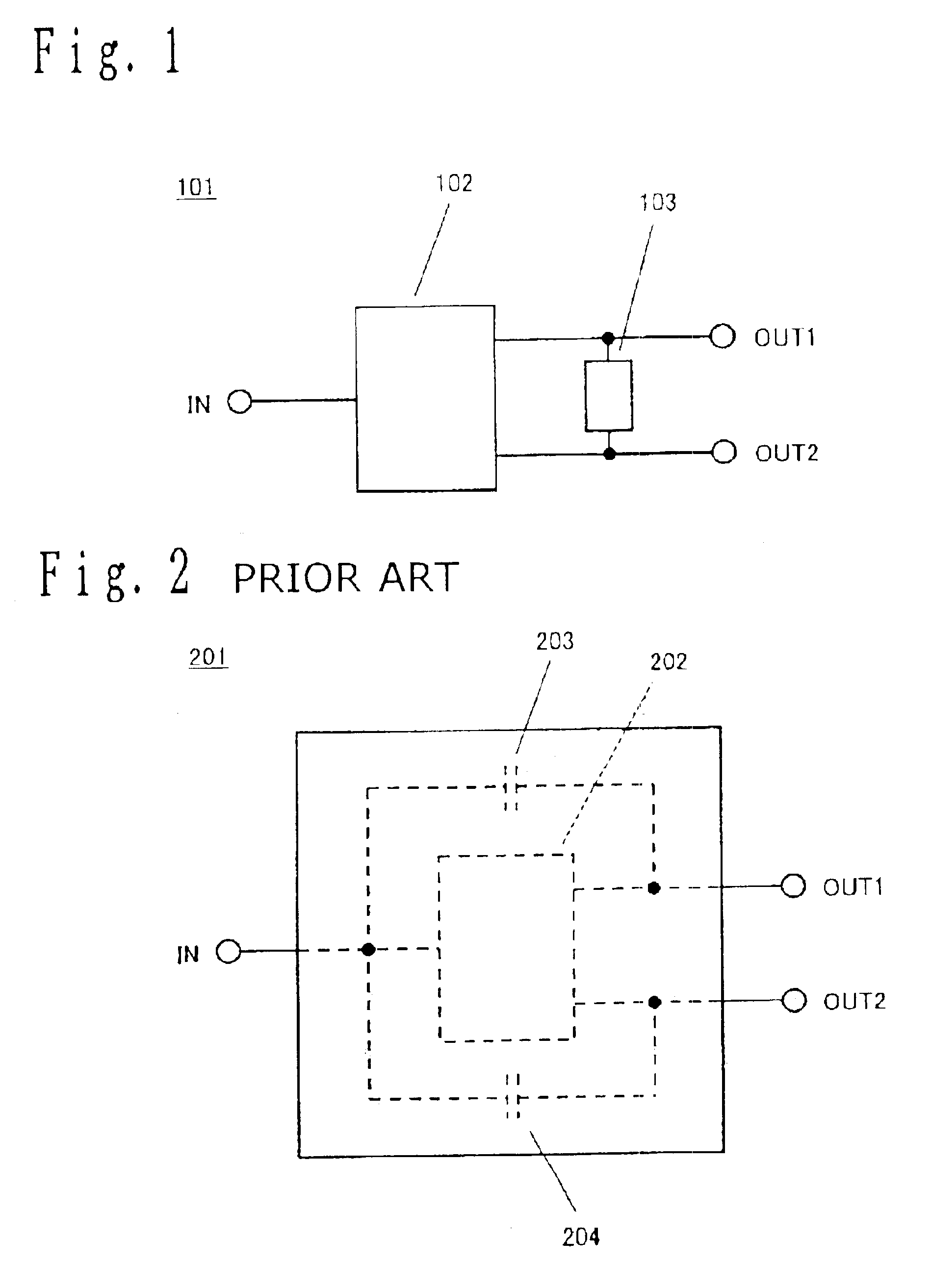
[0247]A balanced high-frequency device of embodiment 1 of the present invention is described below by referring to the accompanying drawings. FIG. 1 shows a configuration of a balanced high-frequency device 101 of the embodiment 1 of the present invention. In FIG. 1, the balanced high-frequency device 101 is constituted by a balanced device 102 and a phase circuit 103. Moreover, in the case of a balanced device 102, the input-side terminal is an input terminal IN serving as an unbalanced input / output terminal and the output-side terminals are output terminals OUT1 and OUT2 serving as balanced input / output terminals. Furthermore, a phase circuit 103 is connected between the output terminals. By using the above configuration, it is possible to realize a balanced high-frequency device having an unbalanced-balanced input / output terminal.
[0248]First, a balance-characteristic deterioration cause of the balanced high-frequency device is studied by using an surface acoustic wave filter. The...
embodiment 2
[0254]A balanced high-frequency device of embodiment 2 of the present invention is described below by referring to the accompanying drawings. FIG. 5 shows a configuration of a balanced high-frequency device 501 of the embodiment 2 of the present invention. In FIG. 5, the balanced high-frequency device 501 is constituted by a balanced device 502 and phase circuits 503 and 504. Moreover, in the case of the balanced device 502, the input-side terminal is an input terminal IN serving as a balanced input / output terminal and the output-side terminals are output terminals OUT1 and OUT2 serving as balanced input / output terminals. By using the above configuration, it is possible to realize a balanced high-frequency device having balanced-balanced input and output terminals.
[0255]Also in the case of the balanced high-frequency device 501 of the present invention, it is possible to realize a balanced high-frequency device excellent in balance-characteristic because the phase circuit 503 operat...
embodiment 3
[0256]A balanced high-frequency device of embodiment 3 of the present invention is described below by referring to the accompanying drawings. A more specific circuit configuration is shown below as a phase circuit. FIG. 6 shows a configuration of a balanced high-frequency device 601 of the embodiment 2 of the present invention. In FIG. 6, the balanced high-frequency device 601 is constituted by a balanced device 602 and a phase circuit 603. Moreover, in the case of the balanced device 602, the input-side terminal is an input terminal IN serving as an unbalanced input / output terminal and output-side terminals are output terminals OUT1 and OUT2 serving as balanced input / output terminals. Furthermore, the phase circuit 603 is constituted by a transmission line 604 and set between output terminals. The transmission line 604 has a length of λ / 2 (in this case, λ denotes a wavelength) which corresponds to a phase shift of 180°. Furthermore, in this case, λ is equal to a frequency in a pass...
PUM
 Abstract
Description
Claims
Application Information
 - R&D
- Intellectual Property
- Life Sciences
- Materials
- Tech Scout
- Unparalleled Data Quality
- Higher Quality Content
- 60% Fewer Hallucinations
Browse by: Latest US Patents, China's latest patents, Technical Efficacy Thesaurus, Application Domain, Technology Topic, Popular Technical Reports.
© 2025 PatSnap. All rights reserved.Legal|Privacy policy|Modern Slavery Act Transparency Statement|Sitemap|About US| Contact US: help@patsnap.com


