Eureka AIR delivers breakthrough ideas for toughest innovation challenges, trusted by R&D personnel around the world.

Self contained transportable life support system

a life support system and self-contained technology, applied in the field of medical devices, can solve the problems of difficult to transport a patient to a remotely located medical facility in a timely manner, require a substantial amount of time, and often be difficult to transport a casualty immediately

Inactive Publication Date: 2005-05-31
INTEGRATED MEDICAL SYST
View PDF70 Cites 140 Cited by
  • Summary
  • Abstract
  • Description
  • Claims
  • Application Information

AI Technical Summary

Benefits of technology

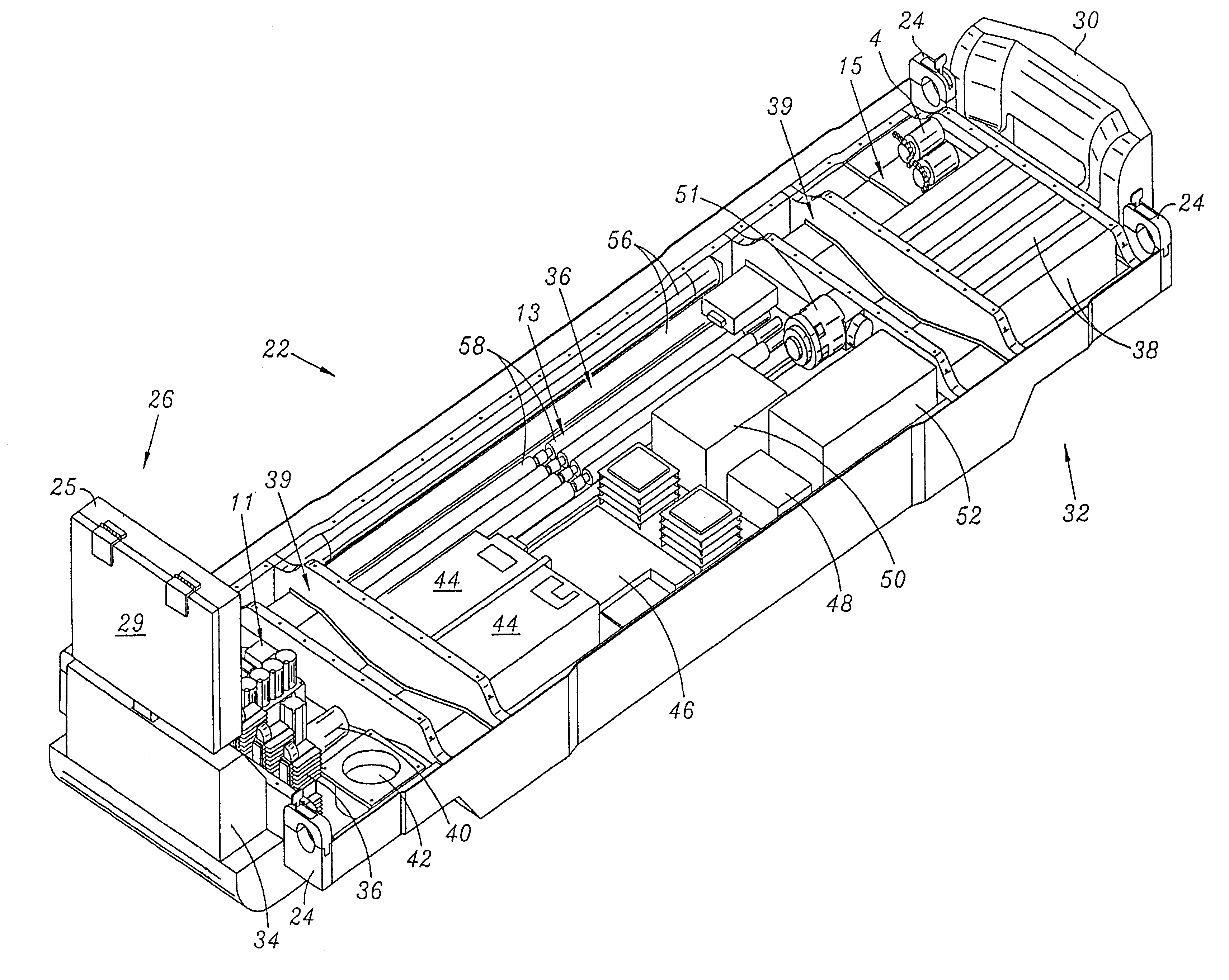
[0053]The housing preferably comprises a hyperbaric chamber and a hypobaric chamber, preferably formed of a lightweight, durable polymer or composite material.

Problems solved by technology

However, as those skilled in the art will appreciate, it is often difficult to transport a patient to a remotely located medical facility in a timely manner, particularly within the golden hour.
Frequently accidents occur at remote locations and thus require a substantial amount of time to transport the medical patient to a distant hospital.
Also, in battlefield situations, it is frequently impossible to transport a casualty immediately.
In either instance, a hospital may be located hundreds, if not thousands, of miles from a hospital, thus necessitating several hours of transport time.
However, disconnection of the medical devices from the patient results in the undesirable disruption of medical monitoring or treatment therefor.
Hand carrying the medical devices along with the patient requires extra personnel, which may not be available, or for which there may not be adequate room within the transport vehicle.
However, since the various medical devices of the MIRF are not integrated with the housing thereof, the inclusion of all of the medical devices results in a system having substantial weight.
Further, since the various medical devices of the MIRF are not integrated with the housing thereof, the volume occupied thereby and the electrical power consumption of the medical devices thereof are not optimal.
However, also like the MIRF, the MOBI is not an integrated system and thus possesses substantially greater weight, volume, and power consumption than desirable.
Although, as discussed above, various different mobile intensive care systems have been proposed, such contemporary mobile intensive care systems are not suitable for transport via military vehicles having standard NATO stretcher holders.
No contemporary mobile intensive care system is known which fits with this envelope.
Thus, such prior art mobile intensive care systems cannot be efficiently carried via such military vehicles.
This means that fewer such battlefield casualties can be transported via a particular military vehicle when such contemporary mobile intensive care systems are utilized, thus inherently causing undesirable delays in transport and also undesirably increasing the risk of mortality.
However, to date, no such life support systems are known which are specifically configured to be compatible with such standard stretcher holders.
Such removal of the medical patient from a contemporary mobile intensive care system may require disconnection from or disruption of desirable medical treatment, thus increasing the risk of mortality.
Further, as those skilled in the art will appreciate, removing a medical patient from a mobile intensive care system, such that the medical patient can be placed upon a stretcher for transport aboard a military vehicle utilizing standard NATO stretcher mounts, tends to exacerbate existing injuries and thus tends to further increase the rate of mortality for such battlefield casualties.
Further, such contemporary mobile intensive care systems require skilled operators having extensive training to assure that proper care is provided to the medical patient.
Further, since the individual medical devices of contemporary mobile intensive care systems are not integrated with one another, the medical care provided thereby is not optimized.
Additionally, such lack of integration necessitates constant monitoring of the medical patient during transport.
Constant monitoring of the medical patient is often either difficult or impossible, since skilled medical personnel are generally either not available or are highly taxed during such evacuation procedures.

Method used


Image

  • Self contained transportable life support system
  • Self contained transportable life support system
  • Self contained transportable life support system

Examples


Embodiment Construction

[0098]The description set forth below in connection with the appended drawings is intended as a description of the presently preferred embodiment of the invention, and is not intended to represent the only form in which the present invention may be constructed or utilized. The description sets forth the functions and the sequence of steps for constructing and operating the invention in connection with the illustrated embodiment. It is to be understood, however, that the same or equivalent functions may be accomplished by different embodiments that are also intended to be encompassed within the spirit and scope of the invention.

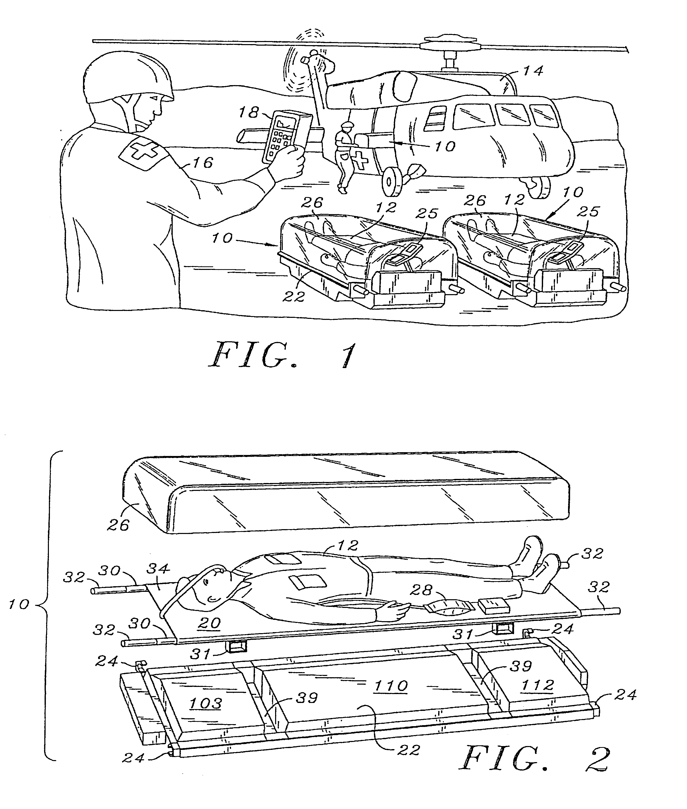
[0099]Although discussed and illustrated herein as having particular application in battlefield situations, those skilled in the art will appreciate that the transportable life support system of the present invention may be utilized in various different civilian applications, such as emergency rescue and medical evacuation. As such, description and illustratio...


PUM


Abstract

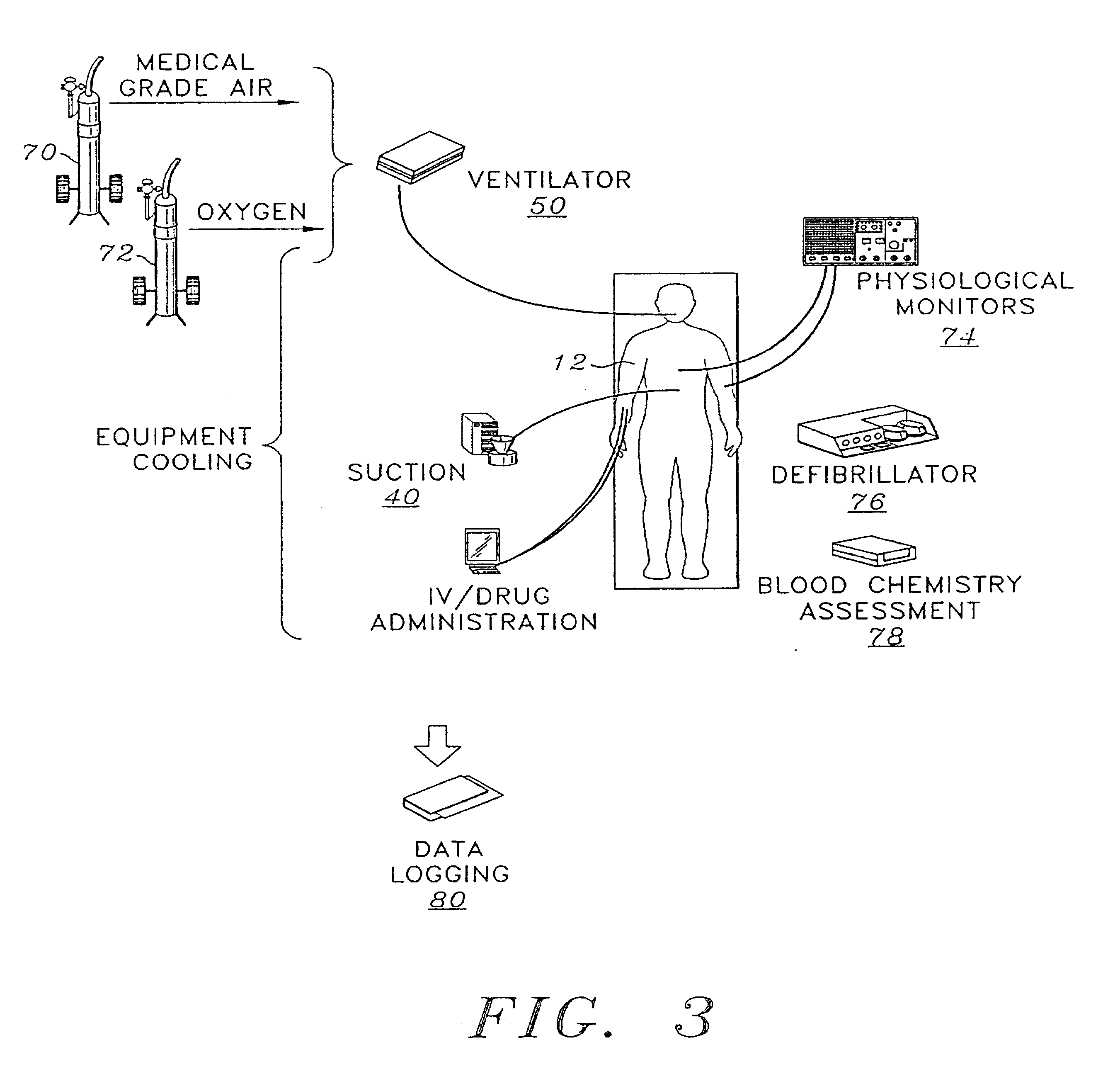
A self-contained transportable life support system for resuscitation, stabilization, and transport of a patient has an environmentally controlled housing for receiving and supporting a patient and a plurality of medical devices disposed within the housing. A control circuit attached to the housing has at least a portion thereof extending to an external surface of the housing for regulating operation of the medical devices and environmental conditions of within the housing in response to monitored life support conditions of the patient.

Description

CROSS-REFERENCE TO RELATED APPLICATIONS[0001]The present application is a continuation of U.S. application Ser. No. 09 / 221,223 entitled SELF-CONTAINED TRANSPORTABLE LIFE SUPPORT SYSTEM filed Dec. 23, 1998, now U.S. Pat. No. 6,488,029, which is a continuation of U.S. application Ser. No. 08 / 667,693 entitled SELF-CONTAINED TRANSPORTABLE LIFE SUPPORT SYSTEM filed Jun. 21, 1996now U.S. Pat. No. 5,975,081.MICROFICHE APPENDIX[0002]This patent application contains a microfiche appendix which contains a program listing for the computer program used in the practice of this invention consisting of 42 sheets and 743 frames.FIELD OF THE INVENTION[0003]The present invention relates generally to medical devices utilized to treat intensive care patients and more particularly to a self-contained transportable life support system which is utilized in the resuscitation, stabilization, and transport of medical patients such as heart attack victims, stroke victims, accident victims and battlefield casu...

Claims


Application Information

Patent Timeline
Patent Type & Authority Patents(United States)
IPC IPC(8): A61G1/00A61G1/04A61G10/02A61G10/00A61M16/00
CPCA61G1/00A61G1/04A61M16/0051A61G2203/46A61G2210/30A61G10/023A61M16/0063A61M16/101A61M16/107A61M16/026A61M2202/0208A61M2202/03A61M2202/0007
Inventor HOOD, DAVID DARBYSHERRILL, DAVIDKNEALE, TODD DOUGLASTOTH, LOUIS STEPHENSTANLEY, DAVID MICHAELMOORE, GENE BRUCEBERRY, MARK LANEGARCIA, ROBERT MICHAELSOBKO, WILLIAM RICHARDHANKS, DONALDSHULTZ, DOUGLAS ELLWOODBRAYTON, JOHN ROGERCLARK, WALTER DENNIS
Owner INTEGRATED MEDICAL SYST
Why Eureka
Eureka Blog
Learn More